
Acta Crystallographica Section B
Acta Crystallographica
Section B STRUCTURAL SCIENCE, CRYSTAL ENGINEERING AND MATERIALS
Acta Crystallographica
Section B STRUCTURAL SCIENCE, CRYSTAL ENGINEERING AND MATERIALS


 menu
|
|
Figure 4
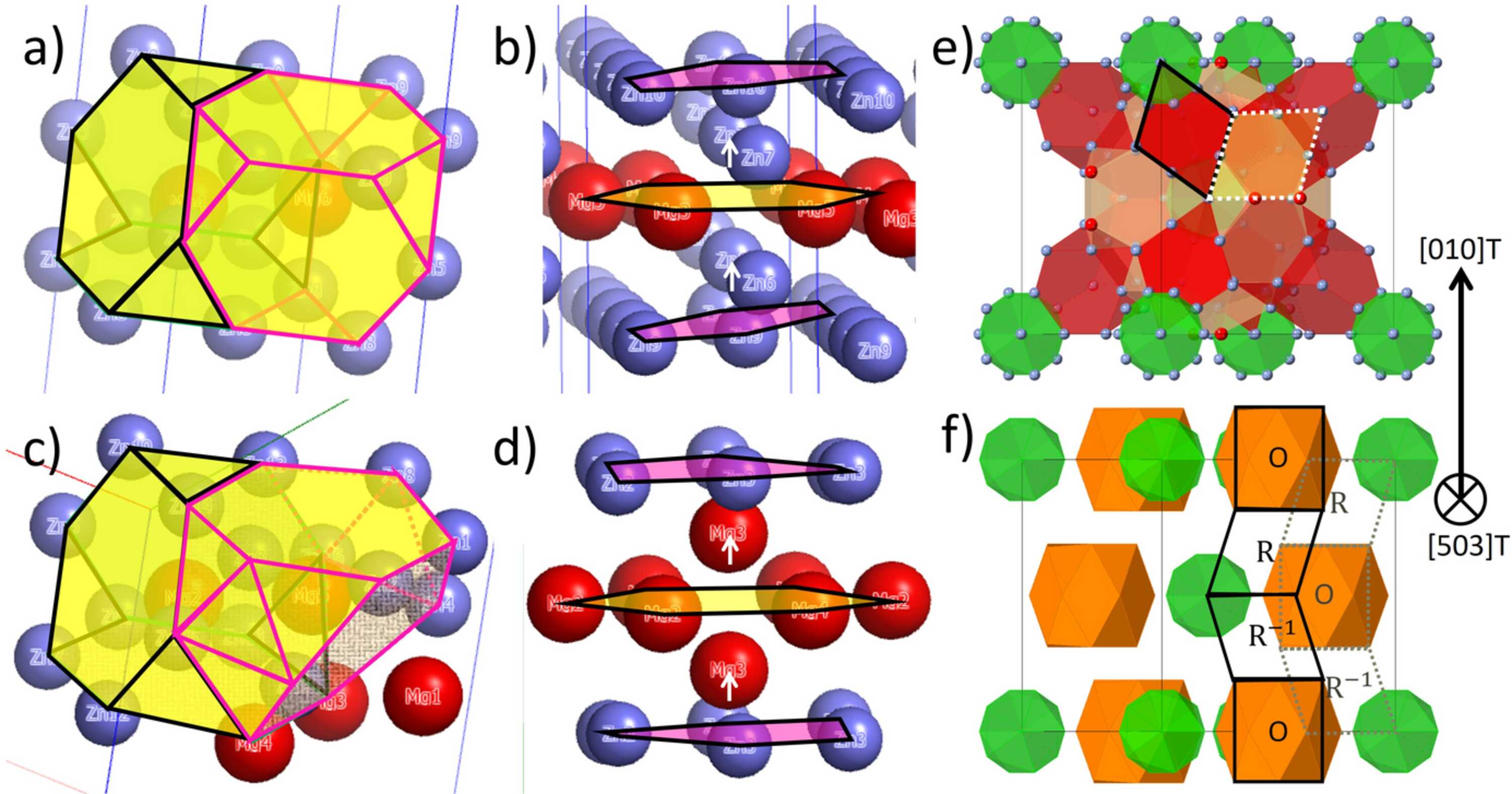
(a) The rhomb unit consists of two connected truncated tetrahedra (TT), marked with black and purple lines, having Mg in the centers and Zn (Cu) as vertices. (b) The orthorhomb unit can be viewed as a barrel with two smaller hexagons on top and bottom made of Zn (Cu) (purple surface), a larger hexagon made of Mg in the center (yellow surface) and two Zn (Cu) atoms, one in between each hexagon along the centerline, marked by white arrows. The atomic model of η′ (Type 1) from Marioara et al. (2013  ) was used to draw the R and O units. (c) Compositionally mixed rhomb unit in T-phase. Some Zn atoms are replaced by Mg, leading to two distorted hexagons drawn with tiled surfaces, and one modified TT into a new unit made by three connected hexagons drawn with purple lines. (d) Orthorhomb (barrel) unit from T-phase. The two Zn atoms in between the hexagons are replaced by Mg [see the white arrows, compare with (b)], leading to a distorted middle Mg hexagon (yellow surface). (e) [503]T projection with icosahedra marked green, perfect rhomb units [as in (a)] marked in red, and modified rhomb units [as in (c)] marked in yellow, with one outlined by white dotted lines. (f) [503]T projection with icosahedra marked in green and barrel units [as in (d)] along [010]T marked in orange. The projections of the compositionally mixed R and O units create ORR−1 and OR−1R stacking sequences (drawn with black and dotted gray lines, respectively). They are formed at different heights of the i5T directions. The T-phase structure from Sun et al. (2000) was used to draw the images in (c) to (f). |
| STRUCTURAL SCIENCE CRYSTAL ENGINEERING MATERIALS |
ISSN: 2052-5206
 access