
Acta Crystallographica
Section B STRUCTURAL SCIENCE, CRYSTAL ENGINEERING AND MATERIALS


 menu


research papers
| STRUCTURAL SCIENCE CRYSTAL ENGINEERING MATERIALS |
 access
Quasi-crystal symmetry and structural connections between precipitates in Al–Mg–Cu–Ag and Al–Zn–Mg(–Cu) alloys

aMaterials and Nanotechnology, SINTEF Industry, Høgskoleringen 5, Trondheim, 7034, Norway, bDepartment of Physics, NTNU, Norwegian University of Science and Technology, Trondheim, 7491, Norway, and cDepartment of Physical Science and Engineering, Nagoya Institute of Technology, 466-8555, Japan
*Correspondence e-mail: [email protected]
The atomic structure of nanosized platelet metastable precipitates in an artificially aged Al–Mg–Cu–Ag alloy has been analyzed by atomic resolution annular dark-field The platelets have habit planes parallel to {111} Al and are structurally related to the η′, η2 phases of the Al–Zn–Mg(–Cu) system and to the T-(Al,Zn)49Mg32 Bergman phase. They consist of compositionally modified rhomb (R) and orthorhomb (O) units stacked across the plate thickness in two unique ORR−1 and OR−1R sequences laterally intertwined. In some precipitates specific stacking faults in the arrangement of such units lead to the formation of two concentric Bergman icosahedra and local fivefold atomic configurations. A fraction of the platelets forms regions isostructural with the T-(Al,Zn)49Mg32 Bergman phase in i5T // 〈112〉Al orientations, having more faceted interfaces. Stacking faults in the lateral arrangements of the icosahedra units lead to local quasi-crystalline atomic configurations.
Keywords: aluminium alloys; phase transformation; quasi-crystal structure; ADF-STEM.
1. Introduction
Due to their excellent combination of properties such as medium strength, good ductility and superior corrosion resistance, Al–Mg alloys are important structural materials used in industries such as marine, automotive, aerospace and construction. They are non-heat treatable, and their strength is mainly derived from Mg in which enhances during deformation. The strength of these alloys can be further improved by the addition of other elements such as Cu which combines with Mg and Al to form metastable nano-sized precipitates during a subsequent artificial aging. The precipitation sequence of these alloys is still not fully understood. For Mg concentrations higher than 2 wt% and Cu above approximately 0.5 wt%, the phase diagram predicts a combination of S and T phases at 463 K (Brook, 1963 ; Vietz & Polmear, 1966), although recent works have concluded that in addition to the metastable S′ phase, Guinier–Preston–Bagaryatsky zones and the structurally unknown Z-phase form in peak-aged conditions (Chopra, 1996; Hirosawa et al., 2006; Mihara et al., 2016). The T-phase in Al–Mg–Cu alloys is isostructural with the T-phase forming in Al–Mg–Zn alloys with high Mg to Zn ratios (Yang et al., 2014). The structure of T-(Al,Zn)49Mg32 was solved in 1957 (Bergman et al., 1957) and was refined by single-crystal X-ray diffraction in 1999 (Sun et al., 2000). It has a body-centered cubic (bcc) unit cell with a = 14.27 Å, Im3 (No. 204), containing 162 atoms. The structure is characterized by icosahedral Bergman clusters located on the corners and in the body center of the unit cell.
Ag additions to the Al–Mg and Al–Mg–Cu alloys greatly increase their precipitation hardening by the nucleation of a high density of fine Z-phases (Chopra, 1996; Hirosawa et al., 2006; Mihara et al., 2016). According to Chopra (1996), the Z-phase has a face-centered cubic (fcc) unit cell with a = 19.99 Å and crystallographic m3m. It is not an isomorph of the T-phase, although it may be structurally related (Mihara et al., 2016). Interestingly, in addition to the Z-phase, an icosahedral quasi-crystalline phase was discovered in peak-aged conditions of an Al–10Mg–0.5Ag (wt%) alloy aged between 20 to 40 min at 513 K (Kubota et al., 2005), and in the peak-aged condition of an Al–3Mg–1Cu–0.4Ag (wt%) alloy aged for 11 days at 443 K (Mihara et al., 2016). A similar quasi-crystalline phase was also found to form during rapid solidification in an additive manufactured AA7075 (Al–Zn–Mg–Cu) alloy (Kairy et al., 2019). It is important to note that the quasi-crystalline phase in Kubota et al. (2005) was oriented as i5 // 〈110〉Al, while in Mihara et al. (2016) its orientation was i5 // 〈112〉Al. The diffraction patterns of the quasi-crystalline phase in all three cases above (Mihara et al., 2016; Kubota et al., 2005; Kairy et al., 2019) are similar. All are characterized by three tenfold rings along the i5 direction with spacings of approximately 3.72 Å, 2.34 Å and 1.43 Å. The ratio between these consecutive numbers approximates the golden ratio, and the last two spacings also correspond to dAl{111} and dAl{220}, respectively, indicating that the quasi-crystalline phase has coherency relationships with the Al matrix and may be metastable. These results point towards a structural connection between the quasi-crystalline phases in the three alloy systems. Kubota observed a similarity between the quasi-crystalline phase and the T-phase in diffraction and composition (Kubota, 2001), which suggests the T-phase is an approximant of the quasi-crystalline phase.
In the present work we are investigating the atomic structure of platelet metastable precipitates with quasi-crystalline configurations observed in the Al–3Mg–1Cu–0.4Ag (wt%) alloy from Mihara et al. (2016). Based on atomic resolution annular dark-field scanning transmission electron microscopy (ADF-STEM) imaging, a structural connection will be demonstrated between this phase and the metastable η′ (Type 1), η2 (Type 2) (Marioara et al., 2013) relating to the Laves η-MgZn2 phase (Friauf, 1927; Komura & Tokunaga, 1980), and with the Bergman T-(Al,Zn)49Mg32 phase (Sun et al., 2000).
2. Experimental
An Al–3Mg–1Cu–0.4Ag (wt%) alloy was mold-casted into 200 mm × 170 mm × 40 mm bulk materials and homogenized for 10 h at 773 K. The billets were rolled into 3 mm-thick sheets at 683 K, and were finally cold rolled to a thickness of 1.2 mm. The plates were solution heat treated for 1 h at 793 K in a salt bath, quenched in ice water and artificially aged for 11 days at 443 K in an oil bath to reach peak hardness condition. The sheets were mechanically thinned to foils of approximately 100 µm thickness from which disks of 3 mm diameter were punched out. TEM specimens were electropolished using a Struers TenuPol-5 unit, with an electrolyte composed of one-third nitric acid and two-thirds methanol kept at 253 K.
To assess the occurrence of the quasi-crystalline phase, the scanning precession electron diffraction (SPED) technique was used to map fivefold diffraction symmetries in sample regions oriented along 〈112〉Al by using a Jeol JEM-2100F TEM operated at 200 kV and equipped with a NanoMegas precession system and a Quantum Detectors Merlin pixelated electron detector (Mir et al., 2017). SPED scans were performed by rastering a converged probe precessed with a rocking angle of 1° over 600 × 600 probe positions using a step size of 1.4 nm. Non-negative matrix factorization (NMF) (Lee & Seung, 1999; Thronsen et al., 2024) was performed to identify regions of the sample contributing strongly to fivefold diffraction symmetries. The average diffraction patterns from these regions were used as templates in a pattern matching scheme to map out precipitates exhibiting fivefold symmetries.
For atomic resolution investigations of precipitate structures, simultaneous acquisition of low angle (LA) and high angle (HA) ADF-STEM images was performed with a probe Cs-corrected Jeol ARM200F TEM operated at 200 kV. The probe size was 0.10 nm and the convergence semi-angle was 27.4 mrad. Inner and outer collection angles were 29 and 51 mrad, respectively, for LAADF-STEM imaging, and 51 and 203 mrad for HAADF-STEM imaging.
LAADF-STEM simulations of the Bergman T-(Al,Zn)49Mg32 phase along its i5T projection were done using py_multislice (Brown et al., 2020). The model has dimensions 83.21 Å × 85.63 Å × 83.21 Å and was simulated using a 2048 × 2048 grid for the potential. The accelerating voltage was set to 200 kV, the convergence angle was 27.4 mrad, and inner and outer collection angles used for the detector were 29 and 51 mrad, respectively. Due to the large model, four frozen phonon iterations were used, with 42 slices per unit cell. Simulations were generated from 10 Å to 80 Å specimen thickness and were convoluted with a Gaussian probe to account for the finite effective source size. The model is published in Thronsen (2025).
3. Results and discussion
The peak hardness condition of the investigated alloy contains a high density of precipitates. When imaged in 〈112〉Al projections, a fraction of the precipitates has platelet morphologies that are viewed edge-on on one set of the {111}Al habit planes, similar to the metastable η′ (Type 1) and η2 (Type 2) precipitates of the Al–Zn–Mg alloy system (Marioara et al., 2013), see Fig. 1. SPED results in Figs. 1(b) and 1(c) show that most of the precipitates with fivefold rotational symmetry have platelet morphologies with low aspect ratio. A total of 567 precipitates were counted in Fig. 1(c), among which 74 (∼13%) displayed fivefold symmetries. As in a {112}Al projection only one of the four non-parallel (distinct) sets of {111}Al planes is viewed edge-on, such particles make up approximately 52% of the total number of precipitates. It can be assumed that the remainder of the precipitates are platelets without fivefold symmetries and Z-phase precipitates. Further studies are necessary to fully clarify the precipitation sequence in these alloys.
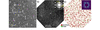 | Figure 1 (a) HAADF-STEM image of precipitates in the peak-aged condition corresponding to 11 days at 443 K of the Al–Mg–Cu–Ag alloy as viewed along 〈112〉Al. Arrows indicate platelets viewed edge-on having one set of {111}Al as habit planes. Dark contrasts represent precipitates etched during the electropolishing process of the TEM sample preparation. (b) Virtual dark-field image of a region probed by SPED. An averaged diffraction pattern from the precipitate indicated with a white dotted circle is included on the top-right. (c) Corresponding phase map shows the distribution of precipitates whose diffraction patterns feature fivefold rotational symmetry. The non-negative matrix factor corresponding to the fivefold diffraction patterns is shown in the top-right corner. The matrix orientation in all images is indicated in (a). |
Based on the morphologies as determined by high-resolution ADF-STEM imaging, the platelet precipitates can be grouped into three categories: (i) platelet precipitates with higher aspect ratio, (ii) platelets with a small growth on one side (matchstick appearance), and (iii) faceted precipitates with low aspect ratio, see Fig. 2 for exemplification.
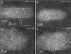 | Figure 2 Raw ADF-STEM images of platelet precipitates: (a) platelet with higher aspect ratio; (b) platelet with small growth on its left-hand side; (c), (d) low aspect ratio, faceted precipitates. All images have the same orientation of the Al matrix as marked in (a). |
A closer inspection of the first category (i), platelet precipitates with higher aspect ratio, reveals striking structural similarities with the metastable η′ and η2 phases from the Al–Zn–Mg system: they consist of stackings of rhomb (R) and orthorhomb (O) units across the plate thickness as seen in 2D projections (Marioara et al., 2013; Thronsen et al., 2023), see Fig. 3.
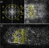 | Figure 3 (a) Fast Fourier transform (FFT) of the HAADF-STEM image in Fig. 2 (a); (b) part of the inverse FFT (IFFT) of (a) formed with the areas inside the circles in (a), giving a filtered, noise-reduced image; (c) IFFT of an LAADF-STEM image of another platelet particle filtered as shown in (a). Rhombs (R) and orthorhombs (O) marked with yellow lines are stacked across the particle's thickness in two distinct laterally intertwined ORR−1 and OR−1R sequences. Stacking faults in (c) are drawn with white lines, sometimes forming fivefold arrangements. Image in (c) has the same scale bar as indicated in (b). |
The rhombs (R) are structural components of the equilibrium η-MgZn2 phase, and of the metastable η′ (Type 1) and η2 (Type 2) precipitates when viewed along their 〈100〉η projections (Marioara et al., 2013). The η-MgZn2 phase is built from a zigzag RR−1 stacking sequence along the c axis. Each rhomb (R) consists of a pair of connected truncated tetrahedra (TT) units, see Fig. 4(a). The orthorhombs (O) are structural parts of the η′ phase in the Al–Zn–Mg(–Cu) system (Marioara et al., 2013), the Ω′ phase in the Al–Cu–Mg–Ag system (Kang et al., 2014; Yang et al., 2022), the T1 phase in the Al–Li–Cu system (Dwyer et al., 2011) and the Y-phase forming at dislocations or (sub)grain boundaries in Al–Zn–Mg–Cu (Zhang et al., 2016; Rhee et al., 2024). It is worth mentioning that, although the orthorhombs in these phases are isostructural, Cu and Zn must replace each other, as well as Li and Mg, while the atoms at the centerline of the Y phase are most likely Al and/ or Mg (Zhang et al., 2016). The orthorhomb (O) unit can be visualized as a `barrel' consisting of two identical smaller hexagons, one on top and one on the bottom formed with Zn (Cu) atoms, a larger middle hexagon formed with Mg (Al) atoms, and two Zn (Cu) atoms, each of them along the centerline in between the small and large hexagon, see Fig. 4(b). The η′ (Type 1) phase is the thinnest platelet metastable phase forming in undeformed matrix (Marioara et al., 2013) and consists of one rhomb layer stacked on one orthorhomb layer plus two modified {111} Al interface planes, totaling a thickness of 6dAl{111}.
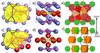 | Figure 4 (a) The rhomb unit consists of two connected truncated tetrahedra (TT), marked with black and purple lines, having Mg in the centers and Zn (Cu) as vertices. (b) The orthorhomb unit can be viewed as a barrel with two smaller hexagons on top and bottom made of Zn (Cu) (purple surface), a larger hexagon made of Mg in the center (yellow surface) and two Zn (Cu) atoms, one in between each hexagon along the centerline, marked by white arrows. The atomic model of η′ (Type 1) from Marioara et al. (2013 ) was used to draw the R and O units. (c) Compositionally mixed rhomb unit in T-phase. Some Zn atoms are replaced by Mg, leading to two distorted hexagons drawn with tiled surfaces, and one modified TT into a new unit made by three connected hexagons drawn with purple lines. (d) Orthorhomb (barrel) unit from T-phase. The two Zn atoms in between the hexagons are replaced by Mg [see the white arrows, compare with (b)], leading to a distorted middle Mg hexagon (yellow surface). (e) [503]T projection with icosahedra marked green, perfect rhomb units [as in (a)] marked in red, and modified rhomb units [as in (c)] marked in yellow, with one outlined by white dotted lines. (f) [503]T projection with icosahedra marked in green and barrel units [as in (d)] along [010]T marked in orange. The projections of the compositionally mixed R and O units create ORR−1 and OR−1R stacking sequences (drawn with black and dotted gray lines, respectively). They are formed at different heights of the i5T directions. The T-phase structure from Sun et al. (2000) was used to draw the images in (c) to (f). |
The 2D projected R and O units in most of the platelet precipitates imaged in this work can be placed in two distinct ways. This can be thought of as two intertwined bases, each of them with a different stacking sequence across the platelet, with either ORR−1 or OR−1R stacking, see Figs. 3(b) and 3(c). This is different from the η′ (Type 1) and η2 (Type 2) precipitates in the Al–Zn–Mg(–Cu) alloys, where the Zn atomic columns with high occupancy defining the corners of the R and O units are unique, and a single basis can be clearly identified in HAADF-STEM images. One RO sequence exists with lateral periodicity in η′, and one sequence comprised of R and/ or R−1 units (no O units) with lateral periodicity exists in η2 (Marioara et al., 2013).
The ORR−1 and OR−1R sequences are disrupted in some precipitates, which leads to the formation of local fivefold atomic configurations, see Fig. 3(c). It has been observed that sometimes such stacking faults accumulate at one end of a plate, producing a small bulge as seen in the precipitate in Fig. 2(b). Under the assumption that the atomic structures of the R and O units of the platelets are identical with the R and O units of the metastable η′ (Type 1) and η2 (Type 2) precipitates in the Al–Zn–Mg(–Cu) alloy system (Marioara et al., 2013), an atomic overlay has been applied on images with the bulge allowing the atomic arrangement of the pentagonal areas to be inferred, see Fig. 5. The overlay in Fig. 5(a) has only considered one choice of basis for the R and O units because the exact atomic structure of precipitates as in Fig. 3 with two sets of intertwined ORR−1 and OR−1R sequences is not yet fully understood.
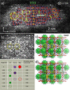 | Figure 5 (a) LAADF-STEM of the precipitate in Fig. 2 (b) filtered as indicated in Fig. 3(a) and overlaid according to the atomic structures of R and O units of the metastable η′ and η2 phases from the Al–Zn–Mg(–Cu) alloy system. (b) Close-up of the left-hand side of the precipitate where fivefold arrangements of the projected atomic columns are observed. (c) Structural similarity of the platelet precipitate in (b) with the atomic structure of the T-phase viewed along its i5T projection, with the icosahedra marked by green surfaces. (d) Structural similarity of the T-phase viewed along its i5T projection with the O and R units of the metastable η′ and η2 phases. The legend corresponds to the atomic overlay in (a) and is based on the atomic structures of the η′ and η2 phases. Similar atomic configurations across images are indicated with similar type of lines. Three types of stacking faults of the R and O units are numbered 1, 2 and 3. |
The result of the atomic overlay in Fig. 5(a) shows that the right-hand side of the precipitate has an atomic structure similar to the metastable η′ and η2 phases of the Al–Zn–Mg(–Cu) system, being comprised of R, R−1 and O units stacked across the platelet thickness, including the compositionally modified {111} Al habit plane at the interface, see the horizontal double-line arrow in Fig. 5(a). Fivefold arrangements of the R units as indicated with yellow lines are also relatively common in the precipitates of the Al–Zn–Mg(–Cu) system (Rhee et al., 2024). However, there are specific faults in the stacking of the R, R−1 and O units in the precipitates shown in Figs. 3(c) and 5(a) that have not been observed in the metastable precipitates of the Al–Zn–Mg(–Cu) system. These faults are marked by `1', `2' and `3' on the atomic overlay in Fig. 5(a). In addition, the characteristic ORR−1 sequence across the platelet thickness is present in this precipitate as well, see Fig. 5(a). Together with the stacking faults it gives rise to fivefold arrangements of the projected atomic columns which are specific for some platelet precipitates in this alloy, see the pentagons marked by continuous white double lines in Figs. 5(a) and 5(b).
The most important observation about these atomic configurations is their similarity with a slice of the T-phase structure when viewed along its fivefold symmetry directions (i5T), for example along 〈m0k〉 with m/k ∼ τ, the golden ratio. Figs. 5(c) and 5(d) show such a projected slice which is close to 〈503〉T orientation, with different structural elements identified. The model of T-(Al,Zn)49Mg32 phase as refined by Sun et al. (2000) was used, see Table 1, and the surfaces of the two concentric icosahedra at the corners and center of the bcc unit cell are marked in green. In this projection, depending on the thickness of the structure, some atoms align in almost perfect columns, while others are misaligned with short lateral separations. The projections of the aligned atoms define fivefold column arrangements of different sizes which match well with the LAADF-STEM image, as indicated in Figs. 5(a), 5(b) and 5(c). Another observation is that atomic columns of the T-phase along i5T can also define corners of rhombs and orthorhombs of similar sizes to those observed in the precipitates of the Al–Zn–Mg(–Cu) system, see Fig. 5(d). Fig. 4(e) shows that the rhomb units in the T-phase are of two types. One type (marked with red surfaces) is isostructural with the two connected truncated tetrahedra (TT) found in the η-MgZn2 and η′, η2 precipitates from the Al–Zn–Mg(–Cu) system [see Fig. 4(a)]. The other type of rhomb is compositionally mixed, with some Zn (Cu) atoms in the vertices of TTs being replaced by Mg, which leads to deformed hexagons and the change of one of the two TTs into a new unit comprising three connected hexagons, as shown on the right-hand side of the structure in Fig. 4(c). This new unit can also be used to define the orthorhombs, which in the T-phase are slightly modified as compared to the η′ phase by having the Zn (Cu) atoms in between the small and large hexagons replaced by Mg, see Figs. 4(b) and 4(d).
| ||||||||||||||||||||||||||||||||||||||||||
Along i5T the T-phase contains R and O units at different depths which overlap in projection, see Fig. 4(f). However, once a choice of basis is made, the ORR−1 or the OR−1R sequence occurring at that specific depth, with compositionally mixed R and O units, can be followed along the 〈100〉T direction perpendicular to the viewing i5T direction [see Figs. 4(e), 4(f) and 5(d)]. Fig. 5(d) also shows that all the stacking faults of the R and O units observed in the platelet precipitates, exemplified in Figs. 3(c) and 5(a), can be traced on the i5T projection of the T-phase, depending on the choice of basis for the projected O and R units.
The presence of the R and O units in both the platelet precipitates without fivefold atomic configurations and in the T-phase indicate the platelets most likely nucleate with structure and coherency similar to the metastable η′ and η2 phases from the Al–Zn–Mg(–Cu) system, having Zn replaced by Cu. With a high driving force to form T-phase, the atomic columns along 〈112〉Al become compositionally mixed, forming modified R and O units [Figs. 4(c) and 4(d)] with the ORR−1 and OR−1R sequences across the platelet thickness, laterally intertwined in local atomic configurations of the T-phase. It is interesting to notice that the intertwined ORR−1 and OR−1R sequences have also been observed in the metastable precipitates of the Al–Zn–Mg(–Cu) alloy system, which indicates their low formation energy. See for example Fig. 7 in Thronsen et al. (2023) and Fig. 1(c) in Yan et al. (2024), where the authors observe the non-unicity of corner choice, and the presence of the two sequences as `domains', similar to our drawing in Figs. 3(b) and 3(c). The implication is that precipitates containing the two intertwined sequences are unique and are structurally different from the Type 2 (η2) which only contains clearly defined R units, and no O units. From now on we will label such precipitates as η′2.
Our work shows that a change in the composition of columns along the `O' and `R' units, accompanied by changes in the interatomic distances between the atoms in these columns, leading to the formation of ORR−1 and OR−1R sequences across the platelet thickness is a necessary, but not sufficient condition for the evolution of these precipitates towards T-phase: specific stacking faults are also needed, as indicated by `1', `2' and `3' in Fig. 5(a). They lead to the formation of Bergman icosahedra and local transformation towards the T-phase structure having orientation i5T //〈100〉η′ // 〈112〉Al, {001}T // {001}η′ // {111}Al. Example of icosahedra formation is observed in the two locations marked by yellow pentagons on the left-hand side of the platelet in Fig. 5(a) and enlarged in Fig. 5(b), when compared to the T-phase structure in Fig. 5(c).
Close investigation of the faceted type of precipitates as in Figs. 2(c) and 2(d) shows a pronounced fivefold arrangement of atomic columns and the existence of configurations consisting of two concentric rings, each containing ten projected atomic columns, marked by green circles in Figs. 6(b) and 7(b). The arrangement of these circles has a close resemblance to the atomic structure of the T-phase viewed along i5T, also demonstrated by the simulated LAADF-STEM images in Figs. 6(c) and 7(c), corresponding to 40 Å thickness, that have a good match with the IFFT filtered images in Figs. 6(b) and 7(b), respectively. The circles correspond with the two concentric icosahedra (Bergman clusters) located at the corners and body centers of the T-phase unit cells, having atoms separated by 2.53 Å and 5.07 Å, respectively. The atoms aligning in almost perfect columns show bright intensities and fivefold arrangements in the images in Figs. 6(b) and 7(b), while those which do not align but have close lateral separations appear as `clouds', matching well with the structure of the T-phase. Therefore, the faceted precipitates might represent a later stage of transformation to T-phase, and the quasi-crystalline atomic arrangements arise from stacking faults and defects in this phase. Figs. 6(c) and 7(c) show that not all the faults in the arrangement of the concentric icosahedra lead to quasi-crystalline structures, but only the horizontal ones (along 〈110〉Al). The vertical stacking faults (along 〈111〉Al) are marked by red stretched hexagons in Fig. 7(c) and do not produce fivefold structures.
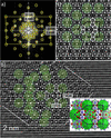 | Figure 6 (a) FFT of the precipitate in Fig. 2 (c) with selected spot masks. (b) IFFT of the areas selected by the spot masks in (a). The outer icosahedra corresponding to the T-phase structure are marked by semi-transparent green circles, and correspondence with the T-phase (lower-right insert) is indicated. The fivefold atomic arrangement is drawn with dashed white lines and the interface with the Al matrix with double white lines. (c) Simulated LAADF-STEM image of the T-(Al,Zn)49Mg32 phase along [503]T at 40 Å thickness. |
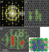 | Figure 7 (a) FFT of precipitate in Fig. 2 (d) with selected spot masks. (b) IFFT of the areas selected by the spot masks in (a). The outer icosahedra corresponding to the T-phase structure are marked by semi-transparent green circles and correspondence with the T-phase (lower-right insert) is indicated in areas marked `1', `2' and `3'. The fivefold atomic arrangements are drawn with thick white lines and the interface with the Al matrix with double white lines. Vertical stacking faults are indicated by the semi-transparent red stretched hexagons. (c) Simulated LAADF-STEM image of the T-(Al,Zn)49Mg32 phase along [503]T at 40 Å thickness. |
The similarity between the atomic structures of the platelet precipitates and the T-phase can also be observed in diffraction, see Fig. 8. Here we compare the simulated kinematical diffraction pattern of the T-phase along i5T using the model in Table 1 with the SPED of a platelet having fivefold rotational symmetry. It can be observed that both patterns contain three concentric rings of ten spots corresponding to approximately 3.72 Å, 2.34 Å (= dAl{111}) and 1.43 Å (= dAl{220}) spacings. The presence of these rings shows that icosahedra typical for the T-phase have already formed in the platelet precipitate.
 | Figure 8 (a) Kinematic diffraction pattern of T-phase along i5T using ReciPro (https://seto77.github.io/ReciPro/) software; (b) SPED pattern from a platelet precipitate along 〈112〉Al. Two concentric rings of ten spots, marked by yellow rings, corresponding to 2.34 Å (= dAl{111}) and 1.43 Å (= dAl{220}) spacings can be clearly identified in both the simulated and the experimental patterns while a third ring with weaker intensity spots corresponding to approximately 3.72 Å spacing is present in the experimental pattern. This ring can also be found in the simulated pattern, with two of the ten spots having a strong intensity. In (a), d-spacings of some spots from the three rings are marked with yellow ovals. |
An important observation is that although the faceted precipitates match well with the i5T projection of the T-phase as described by Sun et al. (2000), the alloy in this work does not contain Zn. This means that the T-phase can form in different Al–Mg–X (X = Zn, Cu, Ag) alloy systems, with Mg likely to preserve its atomic positions in the phase. The atomic sites of Zn in the T-phase formed in the present alloy must be replaced by Al, Cu and Ag. Consequently, Ag is important for the formation of the T-phase with i5T // 〈112〉Al and its associated quasi-crystalline platelet, as this specific orientation has not been reported in Ag-free Al–Mg–Cu alloys.
The results in this work have been obtained with the Al matrix oriented along 〈112〉Al, which is the best viewing direction to visualize the atomic structure of the platelet phase due to its specific coherency with the Al matrix. This direction allows the identification of the barrel (O) and TT (R) units in the early stages of platelet growth, as well as fivefold symmetries and the two concentric rings of ten atomic columns each that correspond to icosahedra of the T phase as viewed along the i5T projection, forming in the later stages of platelet evolution.
4. Conclusions
(i) The platelet precipitates found in the investigated Al–Mg–Cu–Ag alloy contain rhomb (R) and orthorhomb (O) units similar in structure with the metastable η′ and η2 phases from the Al–Zn–Mg(–Cu) system. These units stack across the platelet thickness as two laterally intertwined ORR−1 and OR−1R sequences. Such atomic configurations have also been observed in precipitates forming in Al–Zn–Mg(–Cu) alloys, here labeled as η′2.
(ii) The ORR−1 and OR−1R sequences contain compositionally modified R and O units and are constituents of the equilibrium T-(Al,Zn)49Mg32 Bergman phase.
(iii) Disruptions of the ORR−1 and OR−1R sequences in some platelet precipitates lead to characteristic stacking faults and local atomic configurations of the T-(Al,Zn)49Mg32 phase, characterized by the formation of concentric double icosahedra Bergman clusters, which are a telltale mark for the transformation from η′2 to T-phase. When the transformation is complete, the platelet precipitates acquire a more faceted morphology.
(iv) Defects often arise in the arrangement of the concentric double icosahedra Bergman clusters leading to local quasi-crystalline atomic arrangements in the regions of the platelet precipitates transforming to T-phase.
(v) The SPED analysis shows that platelets forming double icosahedra Bergman clusters, displaying fivefold symmetries when viewed edge-on along 〈112〉Al directions, make approximately 50% of the total number of precipitates in the peak hardness condition of the investigated Al–Mg–Cu–Ag alloy.
(vi) The platelet precipitates can be understood as intermediate stages towards the T-phase formation consisting of the following steps: metastable phases consisting of compositionally modified R and O units with ORR−1 and OR−1R stacking sequences where Al, Cu and Ag occupy Zn positions → specific defects arise in the lateral arrangements of the stacking sequences → formation of concentric double icosahedra Bergman clusters stacked as in the T-phase → faults in the stacking of the Bergman clusters lead to local areas with quasi-crystalline atomic arrangements.
(vii) The orientation relationship with the Al matrix of these phases is [100]η′ // i5T // [112]Al, (001)η′ // (010)T // (111)Al.
Acknowledgements
Open access publishing facilitated by Stiftelsen SINTEF, as part of the Wiley–Stiftelsen SINTEF agreement via SIKT.
Conflict of interest
On behalf of all authors, the corresponding author states that there is no conflict of interest.
Data availability
The data supporting the results reported in this article can be shared upon request.
Funding information
This work was financed by the Research Council of Norway through the Quatrix project (RCN: 316209). The STEM work was carried out on the NORTEM infrastructure (RCN: 197405) at the TEM Gemini Center, Trondheim, Norway. The STEM simulations were carried out on the IDUN cluster at the high-performance computing group at NTNU (Själander et al., 2019).
References
 Bergman, G., Waugh, J. L. T. & Pauling, L. (1957). Acta Cryst. 10, 254–259. CrossRef ICSD CAS IUCr Journals Web of Science Google Scholar
Brook, G. B. (1963). Precipitation in metals. Special Report No. 3. Fulmer Research Institute, UK. Google Scholar
Brown, H., Pelz, P., Ophus, C. & Ciston, J. A. (2020). Microsc. Microanal. 26, 2954–2956. CrossRef Google Scholar
Chopra, H. D. (1996). Philos. Mag. Lett. 73, 351–358. CrossRef CAS Google Scholar
Dwyer, C., Weyland, M., Chang, L. Y. & Muddle, B. C. (2011). Appl. Phys. Lett. 98, 201909. Web of Science CrossRef Google Scholar
Friauf, J. B. (1927). Phys. Rev. 29, 34–40. CrossRef ICSD CAS Google Scholar
Hirosawa, S., Omura, T., Suzuki, Y. & Sato, T. (2006). Mater. Sci. Forum 519–521, 215–220. CrossRef CAS Google Scholar
Kairy, S. K., Gharbi, O., Nicklaus, J., Jiang, D., Hutchinson, C. R. & Birbilis, N. (2019). Metall. Mater. Trans. A 50, 529–533. CrossRef CAS Google Scholar
Kang, S. J., Kim, Y. W., Kim, M. & Zuo, J. M. (2014). Acta Mater. 81, 501–511. Web of Science CrossRef CAS Google Scholar
Komura, Y. & Tokunaga, K. (1980). Acta Cryst. B36, 1548–1554. CrossRef ICSD CAS IUCr Journals Web of Science Google Scholar
Kubota, M., Nie, J. F. & Muddle, B. C. (2005). Mater. Trans. 46, 1278–1287. CrossRef CAS Google Scholar
Kubota, M. (2001). PhD thesis, Monash University, Australia. Google Scholar
Lee, D. D. & Seung, H. S. (1999). Nature 401, 788–791. CrossRef PubMed CAS Google Scholar
Marioara, C. D., Lefebvre, W., Andersen, S. J. & Friis, J. (2013). J. Mater. Sci. 48, 3638–3651. CrossRef CAS Google Scholar
Mihara, M., Marioara, C. D., Andersen, S. J., Holmestad, R., Kobayashi, E. & Sato, T. (2016). Metall. Mater. Trans. A Struct. Mater. Prop. Microstruct. Process. 658, 91–98. CrossRef CAS Google Scholar
Mir, J. A., Clough, R., MacInnes, R., Gough, C., Plackett, R., Shipsey, I., Sawada, H., MacLaren, I., Ballabriga, R., Maneuski, D., O'Shea, V., McGrouther, D. & Kirkland, A. I. (2017). Ultramicroscopy 182, 44–53. CrossRef CAS PubMed Google Scholar
Rhee, Y., Thronsen, E., Ryggetangen, O., Marioara, C. D., Holmestad, R. & Kobayashi, E. (2024). Met. Mater. Int. 30, 3294–3310. CrossRef CAS Google Scholar
Själander, M., Jahre, M., Tufte, G., Reissmann, N. (2019). EPIC: An energy-efficient, high-performance GPGPU computing research infrastructure. DOI: 10.48550/arXiv.1912.05848. Google Scholar
Sun, W., Lincoln, F. J., Sugiyama, K. & Hiraga, K. (2000). Mater. Sci. Eng. A 294–296, 327–330. CrossRef Google Scholar
Thronsen, E., Bergh, T., Thorsen, T. I., Christiansen, E. F., Frafjord, J., Crout, P., van Helvoort, A. T. J., Midgley, P. A. & Holmestad, R. (2024). Ultramicroscopy 255, 113861. Web of Science CrossRef PubMed Google Scholar
Thronsen, E. (2025). Model for Atomic structure of platelet precipitates in an artificially aged Al–Mg–Cu–Ag alloy. DOI: 10.5281/zenodo.14760988. Google Scholar
Thronsen, E., Shah, S., Hatzoglou, C., Marioara, C. D., Wenner, S., Andersen, S. J., Holmedal, B. & Holmestad, R. (2023). J. Mater. Res. Technol. 23, 5666–5680. CrossRef CAS Google Scholar
Vietz, J. T. & Polmear, I. J. (1966). J. Inst. Met. 94, 410–416. CAS Google Scholar
Yan, L., Sun, Y., Zhang, Y., Wang, S., Tang, H., Li, L. & Ge, B. (2024). Mater. Charact. 218, 114486. CrossRef Google Scholar
Yang, S. L., Zhao, X. J., Chen, H. W., Wilson, N. & Nie, J. F. (2022). Acta Mater. 225, 117538. CrossRef Google Scholar
Yang, X. B., Chen, J. H., Liu, J. Z., Qin, F., Xie, J. & Wu, C. L. (2014). J. Alloys Compd. 610, 69–73. CrossRef CAS Google Scholar
Zhang, Y., Weyland, M., Milkereit, B., Reich, M. & Rometsch, P. A. (2016). Sci. Rep. 6, 23109. CrossRef PubMed Google Scholar
This is an open-access article distributed under the terms of the Creative Commons Attribution (CC-BY) Licence, which permits unrestricted use, distribution, and reproduction in any medium, provided the original authors and source are cited.
| STRUCTURAL SCIENCE CRYSTAL ENGINEERING MATERIALS |