

 menu
|
|
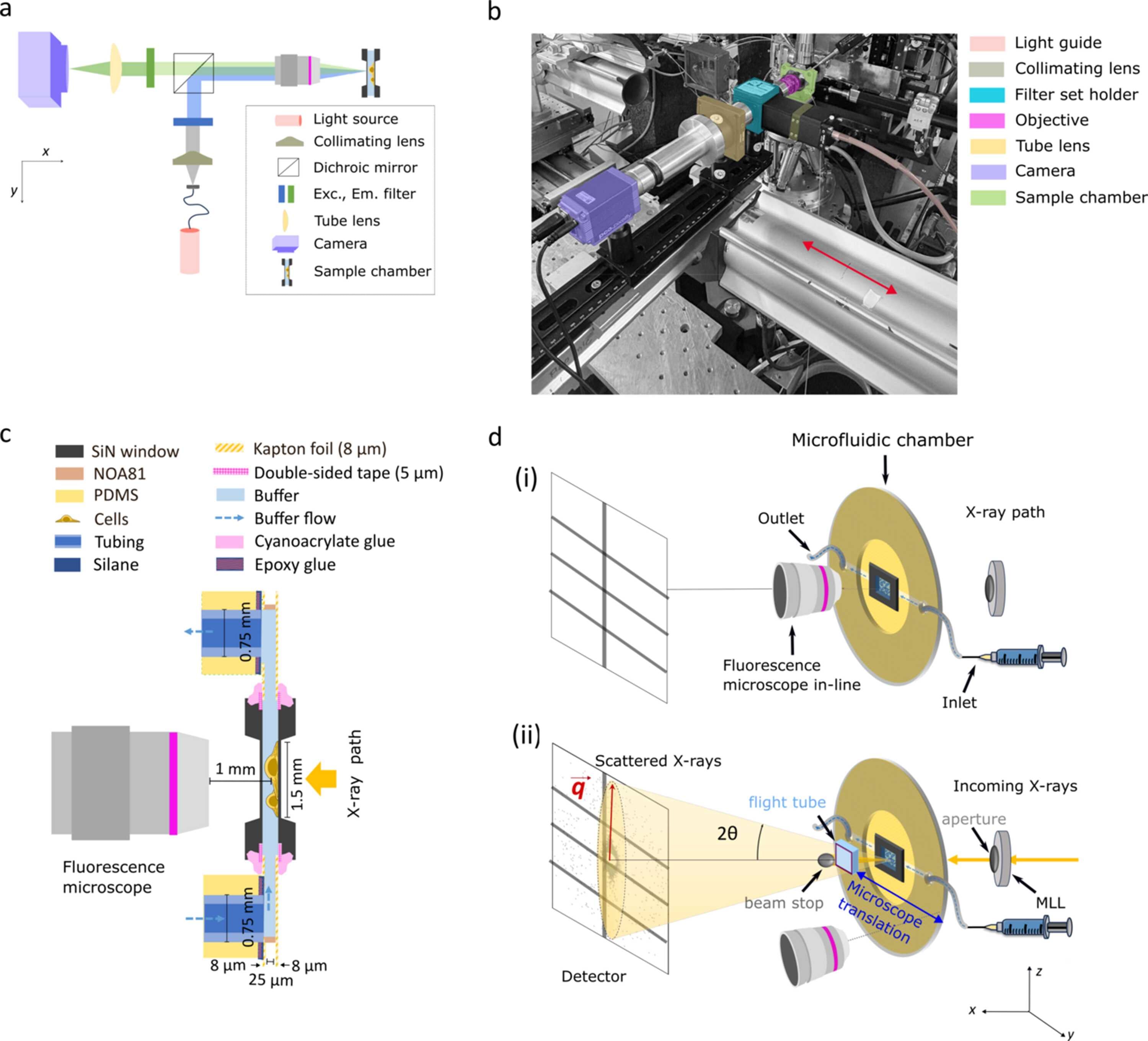
Figure 1
Integrated fluorescence microscopy and microfluidic sample environment for multi-modal correlative imaging at a synchrotron beamline. (a) Schematic of the home-built epi-fluorescence microscope showing the optical layout optimized for integration in the beamline. (b) Photograph of the microscope installed at the beamline (ESRF, ID13). The relevant optical components are highlighted in different colors. In this geometry the sample stays in the X-ray beam path; fluorescence imaging is performed sequentially to the X-ray measurements by shuttling the microscope in and out of the X-ray beam path, as indicated by the red arrow. (c) Side-view schematic of the fully assembled microfluidic chamber and the geometry of the setup with the fluorescence microscope in-line while imaging. See legend for the components of the flow chamber and Fig. S2 of the supporting information for a step-by-step explanation of the assembly. (d) Schematic of the integrated experimental setup (not to scale). (i) Microscopy mode. The home-built fluorescence microscope aligned with the microfluidic chamber for imaging. In this mode, no incoming X-ray beam is present. (ii) Fast scanning SAXS mode. The microscope is moved out of the X-ray path to enable fast scanning SAXS measurements. The incoming X-rays are focused by multilayer Laue lenses (MLLs), followed by an aperture placed downstream the MLLs, before illuminating the cells present in the microfluidic chamber. The primary beam is blocked by a beam stop and the scattered signal is collected by the detector. The red arrow illustrates the direction of the corresponding scattering vector q for a scattering angle (2θ). The biological cells are maintained in a thin hydration layer between two Si3N4 windows integrated in the microfluidic chamber, including an inlet (connected to a syringe) and an outlet for continuous buffer flow. |
 | JOURNAL OF SYNCHROTRON RADIATION |
ISSN: 1600-5775
 access