

 menu
|
|
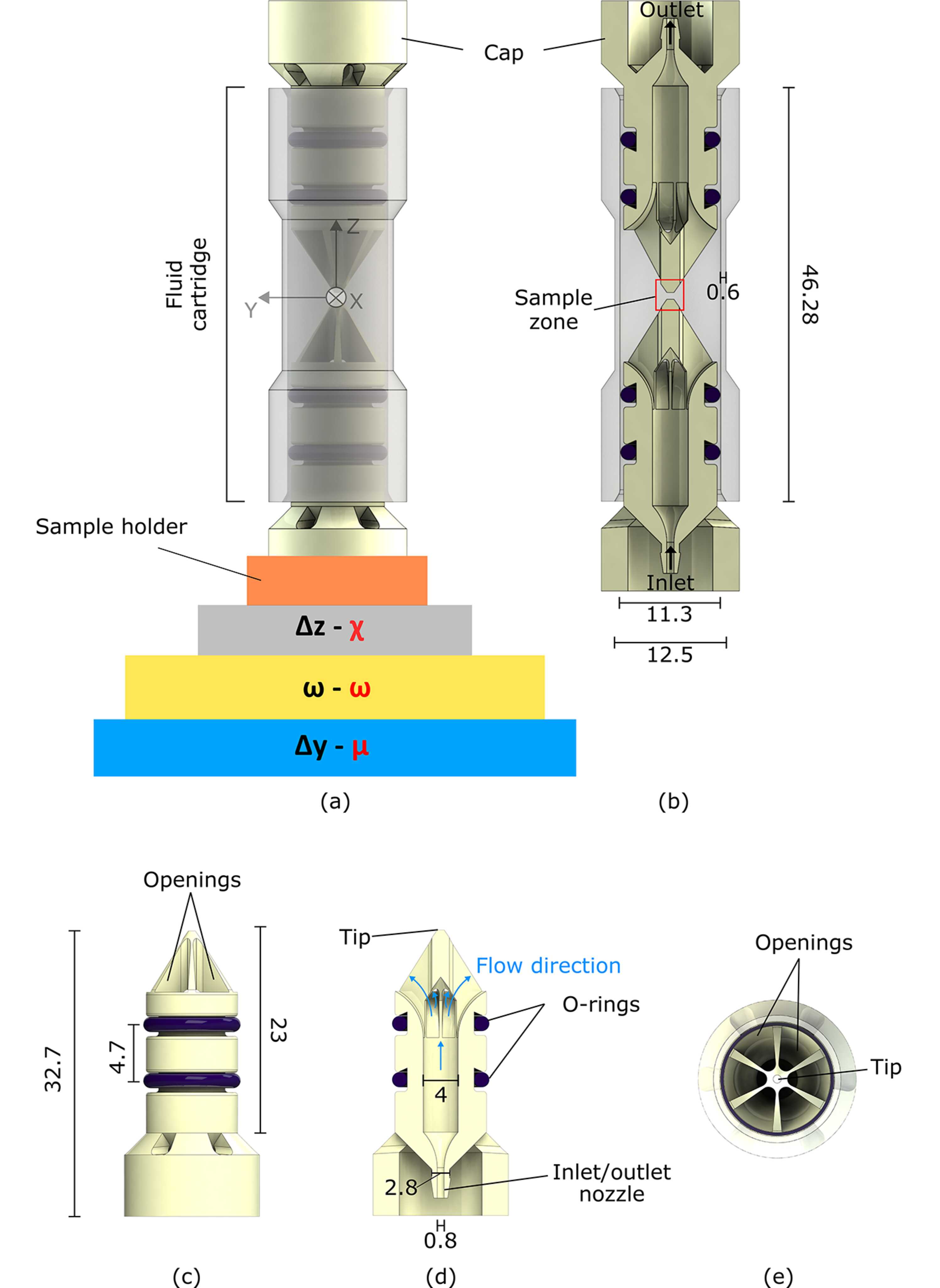
Figure 1
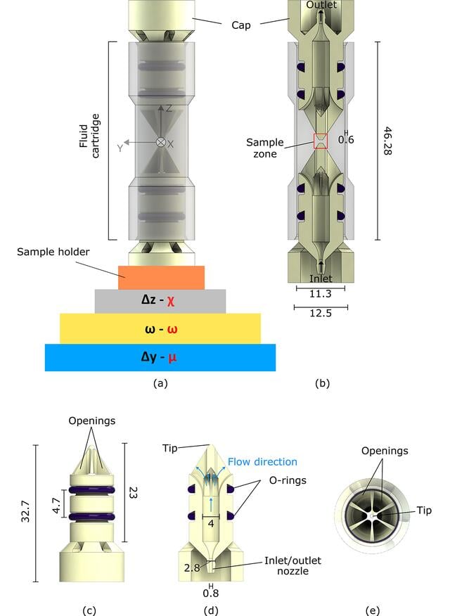
(a) A 3D render of the whole flow cell, with the motor stacking at both ID11 (in black; Δy: translation along the laboratory Y-axis; ω: rotation around the laboratory Z-axis; Δz: translation along the laboratory Z-axis) and ID03 (in red; μ: rocking angle around the laboratory Y-axis; ω: rotation around the laboratory Z-axis; χ: rotation around the laboratory X-axis). (b) A vertical section of the cell. (c) 3D render of one cap. (d) Vertical cross-section of the cap in (c). (e) Top view of the cap showing the six equally spaced openings for the fluid circulation. All dimensions are in mm. |
 | JOURNAL OF SYNCHROTRON RADIATION |
ISSN: 1600-5775
 access