

 menu


research papers
 | JOURNAL OF APPLIED CRYSTALLOGRAPHY |
 access
Crystal shape and lattice deformation in powder diffraction

aResearch and Analytical Services Department, Saudi Aramco, PO Box 62, Dhahran, 31311, Saudi Arabia, bPhysical Sciences, Diamond Light Source (United Kingdom), Diamond House – Harwell Science and Innovation Campus, Didcot, Oxfordshire OX11 0DE, United Kingdom, cEarth and Atmospheric Sciences Department, Indiana University Bloomington, 1001 E 10th Street, Bloomington, IN 47408, USA, and dTechnische Fakultät, Friedrich-Alexander-Universität Erlangen-Nürnberg, Cauerstrasse 3, Erlangen, Bavaria 91058, Germany
*Correspondence e-mail: [email protected], [email protected]
Accurate modelling of diffraction peak shapes is essential for extracting microstructural information from nanocrystalline materials. Common volume functions are widely used to describe finite-size and shape broadening in powder diffraction, but analytical expressions are available only for a limited set of ideal geometries. Here, we introduce a generalized Fourier-based framework in which crystal-domain shape deformation, lattice deformation and relative shape–lattice misorientation are treated as independently refinable tensor operations within a unified formalism. The approach enables continuous affine transformations representing both crystal shape and lattice base deformations while preserving analytical evaluation of directional Fourier coefficients. As a result, complex particle shapes, anisotropic deformations, and arbitrary relative orientations between shape and lattice can be modelled within a single reciprocal- and real-space framework, including coupled shape–lattice transformations not accessible using conventional powder-diffraction line-profile analysis methods. The formalism can be applied to individual diffraction peaks, full powder patterns and total-scattering shape corrections. Validation against virtual scattering experiment data demonstrates that, through full-profile total-scattering analysis, crystal size, shape, lattice deformation and relative shape–lattice orientation can be recovered simultaneously with high accuracy.
Keywords: whole powder pattern modelling; whole pair-distribution-function modelling; shape function; common volume function; domain shape deformation; lattice deformation; line-profile analysis; total scattering; powder diffraction..
1. Introduction
Nanocrystals underpin a wide range of modern and emerging technologies, with their functional behaviour governed not only by atomic-scale structure but also by crystal shape and its coupling to structure. After decades of fundamental innovation, shape-controlled nanocrystal synthesis is approaching industrial application (Li et al., 2023 ; Nguyen et al., 2023; National Science Foundation, 2024). In many systems, however, functional properties arise from a coupled interplay between structure and shape deformation, rather than from either factor alone (Boukouvala et al., 2021; Crisp & Singh, 2024). Experimental studies have also shown that nanocrystal morphologies can evolve substantially under chemical and physical stimuli, including thermal annealing, surface diffusion, strain relaxation and solid–solid phase transformations, directly linking morphological evolution to underlying structural rearrangements (Fichthorn & Yan, 2021; Waitz et al., 2009; Du et al., 2017; Wang et al., 2016).
Characterization of large nanoparticle ensembles requires techniques capable of probing both structure and shape with statistical relevance. Transmission electron microscopy (TEM), particularly high-resolution TEM, provides direct real-space insight into individual nanocrystals and is indispensable for identifying crystal structure, defect and local surface terminations. Recent advances in automated and machine-learning-assisted image analysis have further improved throughput and reproducibility, enabling statistically meaningful population-level analysis of size and shape distributions (Aviles & Lear, 2025; Neumann & Rafaja, 2024; Cho et al., 2024). However, despite these advances in synthesis and characterization, systematically distinguishing shape effects from lattice deformation remains a central challenge in nanoscience. TEM-based approaches are fundamentally limited in capturing coupled shape–lattice evolution across ensembles. While imaging provides detailed local structural and morphological information, it does not directly reveal how shape anisotropy and lattice deformation co-evolve or correlate across reciprocal space. In particular, subtle shape-induced lattice rotations or coupled deformation modes are difficult to quantify reliably, especially in size-dispersed ensembles or systems with concurrent strain relaxation and surface reconstruction.
Powder diffraction, by contrast, is intrinsically sensitive to such coupled effects through their influence on peak broadening, asymmetry and profile shape. Nevertheless, conventional diffraction models generally require predefined particle shapes and fixed shape–lattice orientation relationships, preventing direct recovery of coupled deformation and relative shape–lattice rotation from ensemble-averaged data. This problem is particularly acute in quantitative diffraction analysis, where crystal shape and lattice distortions are inherently coupled. Most analytical approaches still treat them as independent contributions, implicitly assuming a fixed relative orientation between crystal shape and crystallographic axes. This assumption limits the ability to quantify shape rotations, facet distortions and anisotropic reshaping relative to the underlying lattice. As a result, shape–lattice misorientation and coupled deformation modes remain largely inaccessible within standard diffraction-based frameworks, highlighting the need for methodologies that treat shape and lattice structure as independent, yet interacting, degrees of freedom.
The modelling of anisotropic peak broadening in powder diffraction has been approached through several complementary frameworks. Conventional reciprocal-space strain models, such as the Stephens (1999) formalism, describe anisotropic broadening phenomenologically via strain tensors within Rietveld refinement, but they do not explicitly represent finite crystallite shape or its orientation relative to the lattice. Classical size–strain methods, including the Scherrer equation and Williamson–Hall analysis (Khorsand Zak & Hashim, 2025; Mohan et al., 2024), provide simple estimates of average crystallite size but inherently conflate size and strain contributions. Spherical-harmonics-based approaches, such as the Popa (1998) formalism, offer more flexible anisotropic descriptions, yet their coefficients lack direct geometric interpretation in terms of explicit shape or lattice deformation. Overall, these methods rely on strong simplifying assumptions and often conflate size and lattice-distortion effects.
Meanwhile, more physically grounded treatments have been developed (Scardi et al., 2004; Ungár et al., 1998; Brandstetter et al., 2008), including real-space and Fourier-based methods. Pair distribution function (PDF) analysis (Egami & Billinge, 2003) probes local atomic structure but has comparatively limited direct sensitivity to morphology and finite-size shape effects. In contrast, analytical approaches based on the common volume function (CVF) and Fourier-based methods such as Warren–Averbach analysis (Warren & Averbach, 1950; Warren & Averbach, 1952) and whole powder pattern modelling (WPPM) (Scardi & Leoni, 2002; Scardi, 2020; Leoni, 2019) explicitly connect finite crystallite shape to diffraction profiles. However, these methods are typically restricted to idealized geometries or fixed shape–lattice orientation relationships. Extended approaches combining diffraction and total scattering, including whole PDF modelling (WPDFM) (Leonardi, 2021), extend applicability across length scales but still rely on constrained structural assumptions.
At the atomistic level, the Debye (1915) scattering equation removes explicit assumptions on shape and lattice symmetry, but its computational cost scales quadratically with atom number, limiting its practical use in iterative refinement of diffraction profiles. Fourier- and CVF-based approaches such as WPPM and WPDFM reduce computational complexity by exploiting reciprocal–real-space relationships, but still inherit constraints related to predefined crystal shape and fixed lattice reference frames.
Across all these approaches, a common limitation persists: crystal shape, lattice deformation and their relative orientation are not treated as independently variable quantities. Most models implicitly impose a fixed coupling between shape and crystallography or rely on predefined geometries selected a priori. As a result, cases in which shape deformation and lattice deformation evolve simultaneously and with independent orientation cannot be uniquely resolved from powder-diffraction data.
To overcome these limitations, Fourier-based approaches have been extended to describe a range of crystallite shapes, including simple shapes such as spheres, cubes, cylinders, tetrahedra and octahedra, which are frequently used as reference models in diffraction analysis (Scardi & Leoni, 2001; Leoni, 2019). Beyond these closed-form solutions, numerical approaches have been developed for arbitrary polyhedral and complex shapes, including hollow or irregular particles (Leonardi et al., 2012). Building on these ideas, Allegra & Wilson (1983) introduced a framework in which diffraction profiles are derived from linear transformations applied to reference shapes, enabling analytical construction of ellipsoidal and parallelepiped domains from spherical and cubic references. Although widely revisited and extended (Balic-Žunić & Dohrup, 1999; Ectors et al., 2015), these approaches still rely on a fixed relationship between crystal lattice and shape axes and typically treat shape as a rigid or preselected entity rather than a continuously deformable variable.
This limitation is particularly restrictive for modern nanomaterials, where morphology can evolve continuously under growth, strain or phase transformation conditions. Here, we introduce a unified framework that provides an intermediate description between phenomenological anisotropic broadening models and fully atomistic scattering calculations. The central idea is the introduction of distinct affine operators acting separately on (i) the crystallographic lattice and (ii) the finite crystallite domain within a common Fourier/CVF formalism. This formulation enables crystal shape deformation, lattice deformation and their relative misorientation to be treated as separately refinable yet coupled parameters while preserving the analytical tractability of directional Fourier coefficients.
Lattice and shape deformations affect diffraction profiles differently: lattice deformation primarily manifests through peak-position shifts, whereas shape deformation mainly influences finite-size broadening and shape-dependent fringe features, resulting in generally weaker and more subtle diffraction signatures. By extending the linear transformation concepts originally proposed by Allegra and Wilson, we examine how powder-diffraction profiles evolve under independent deformations of (i) domain shape, (ii) lattice geometry or (iii) both simultaneously. As an example, starting from cubic reference domains and lattices, the framework naturally extends to parallelepiped domains in cubic lattices, cubic domains in triclinic lattices, and fully coupled deformations involving both shape and lattice transformations. This separation of shape and crystallographic symmetry, together with their relative orientation in space, allows diffraction profiles to be expressed in a locally defined reciprocal-space representation, facilitating integration into WPPM- and WPDFM-based refinement schemes. Hence, the proposed formalism can be readily implemented in existing whole-pattern analysis software for powder-diffraction (PD) line-profile analysis (Scardi et al., 2018; Scardi, 2020; Leoni et al., 2006; Yakovlev et al., 2019; Leoni, 2014).
A key consequence of this formulation is that crystal shape and lattice symmetry are no longer rigidly coupled. This is particularly relevant for nanocrystals exhibiting anisotropic growth, strain-driven phase transformation or shape-controlled synthesis, where external morphology is not necessarily aligned with crystallographic axes. Because many nanoscale systems exhibit non-crystallographic morphologies in which geometric and atomic ordering are strongly intertwined (Nguyen et al., 2023; Xia et al., 2009; Marks & Peng, 2016), the proposed framework enables direct extraction of shape–lattice orientation and deformation parameters from powder-diffraction data without imposing crystallographic constraints on shape. We demonstrate the practical utility of the approach through analysis of shape-driven phase transformations in metal–alloy nanocrystals, where the relationship between initial and transformed states can be explicitly tracked. To our knowledge, this work presents the first generalized affine-deformation extension of the CVF/WPPM formalism enabling independently refinable shape and lattice deformations.
2. Theory
2.1. Shape and lattice deformation configurations
To classify the deformation state of a given domain, which may involve all shape and lattice deformation and rotation, it is useful to encode the chosen combination of operations in a compact and unambiguous form. We therefore introduce a single integer label obtained from the binary representation of the applied deformation and rotation operations. To achieve this, we define a vector

where [SR], [SD], [LR], [LD] are binary flags indicating whether the corresponding operation is applied. The letters denote shape (S) or lattice (L), and rotation (R) or deformation (D). For example, the vector representing a combined shape rotation [SR] and lattice deformation [LD] is  . These four binary values can be interpreted as the bits of a 4-bit number; in this example, the sequence 1001 corresponds to the decimal value 9. In total, 16 combinations are possible, although only half are non-redundant. Table 1 summarizes the complete set. Note that these relationships are independent of the specific lattice symmetry or the numerical values of the size and deformation parameters.
|
||||||||||||||||||||||||||||||||||||||||||||||||||||||||
 and its corresponding decimal representation are listed together with the equivalent deformation cases and an illustrative example of the resulting deformation/rotation relative to the undeformed reference state (case 0).


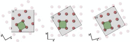
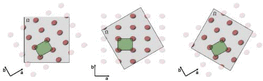
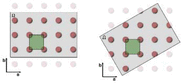
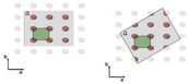
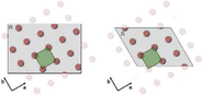
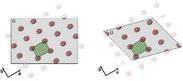
Certain manifestations of these configurations have previously been treated through dedicated analytical descriptions of particular crystal morphologies. However, to the best of our knowledge, a general formulation based on affine transformations of the CVF has not previously been presented. The framework below provides such a formulation and encompasses all deformation configurations listed in Table 1 as particular cases. Existing Fourier/CVF approaches can describe some of these configurations only for specific reference geometries, such as spheres, ellipsoids or a limited number of polyhedra with fixed orientation relative to the crystallographic basis, for which dedicated analytical expressions are available or can be derived ad hoc. In contrast, the present affine formulation separates the lattice and shape transformations from the analytical description of the reference CVF, thereby extending these deformation modes to arbitrary crystal shapes and arbitrary relative shape–lattice orientations without requiring shape-specific derivations. Notably, the configurations (0, 1, 0, 1) and (1, 1, 1, 1) discussed in Sections 3.5 and 3.6 represent the most general combinations of independent shape and lattice transformations and serve as the clearest illustration of the additional flexibility enabled by the theory presented here.
2.2. Deformations of the crystal lattice and domain shape
The calculation of the PD profile from powders composed of monodisperse, monoatomic crystalline domains provides the reference framework for the generalized treatment developed in this work. The mathematical and crystallographic foundations underlying this formalism follow the established approaches commonly used in crystallography, total scattering and line-profile analysis (Coelho, 2018; Giacovazzo, 2011; Warren, 1990; Shmueli, 2010; Krawitz, 2001; Scardi et al., 2018; Scardi & Leoni, 2002; Leoni, 2014) and are summarized in the appendices. Appendix A introduces the geometric framework of direct and reciprocal space, including the metric tensor [equation (33)], unit-cell volume [equation (34)], interplanar spacing relation [equation (35)], orthogonalization matrix [equation (36)] and reciprocal-space coordinates [equation (38)], together with their roles in defining distances, angles, scalar products and reciprocal-space representations. Appendix B summarizes the deformation tensors representing the affine transformations of the lattice and domain, together with their action on metric tensors and reciprocal vectors. Appendix C outlines the WPPM formalism and the Fourier treatment of diffraction from finite crystalline domains. These concepts establish the notation and mathematical framework adopted throughout the following derivations. To preserve analytical tractability and the validity of the Fourier-based treatment, the discussion is restricted to defect-free crystalline domains, or to systems containing only dilute defects for which lattice periodicity remains effectively preserved. Table 2 summarizes the notation adopted throughout the following derivations. Shape deformation tensors ( ) are treated as passive affine transformations acting through pull-back operations on the domain coordinates, allowing the Fourier integrals to be expressed in the reference configuration. In contrast, lattice deformation tensors (
 ) are treated as active push-forward transformations acting on the lattice basis and metric tensor, mapping the reference lattice onto the physical crystal lattice. Together, these derivations establish a general framework for line-profile analysis (LPA) of powder-diffraction data from finite crystalline domains exhibiting shape and/or lattice deformations and non-rigid shape–lattice orientation relationships.
|
||||||||||||||||||||||||||||||||||||||||||||||||||||||||||||||||||||


The following subsections introduce the theoretical developments that extend the formalism described in the appendices to the deformation cases summarized in Section 2.1 and form the basis of all application examples presented in Section 3. Specifically, Sections 2.2.1, 2.2.2 and 2.2.3 develop a unified framework for treating shape deformations, lattice deformations and their mutual coupling, respectively. For each case, we show how the indicator function (and the associated CVF providing the shape Fourier coefficients), the lattice mapping and the corresponding shape deformation operators are modified under the applied deformation and how these modifications propagate consistently into the calculated diffraction profile. To facilitate reproducibility and practical implementation, the complete set of transformation equations is accompanied by a reference implementation provided as supporting information. The accompanying workbook automatically evaluates, for arbitrary lattice metrics, shape and lattice transformation matrices, and selected reflections, the corresponding WPPM parameters, including the transformed reciprocal-space vector, the CVF coefficients, the truncation length, and the associated volume and length rescaling factors. The workbook also generates plots of the undeformed and deformed indicator functions and CVFs, allowing direct comparison of the underlying geometric transformations. For simplicity, the reference implementation is restricted to cubic crystallites. Other crystallite morphologies can be readily incorporated by updating the H - and K-coefficient expressions according to the corresponding analytical CVF formulations reported in the literature (Scardi & Leoni, 2001; Leonardi et al., 2022).
2.2.1. Domain shape deformation with fixed lattice
Shape deformation in the absence of lattice distortion can be efficiently introduced by applying a linear transformation to a known monoparametric reference shape through a diagonal deformation tensor  . This operation produces a domain whose shape is `stretched', either elongated or contracted, along the principal axes while the underlying lattice remains unchanged [Table 1, case 4,
 ]. In this sense, the treatment parallels the results of Allegra & Wilson (1983), but now it is formulated within a fully Fourier-based framework. Including a rotational component in the deformation tensor allows the deformed shape to be oriented arbitrarily with respect to the lattice basis [Table 1, case 4,
 ], enabling, for example, the modelling of anisotropic growth along any crystallographic direction.
For practical computation, it is advantageous not to transform the shape function directly. Instead, the deformation is represented through a transformed virtual lattice in which the deformed domain is mapped onto the undeformed reference geometry (Fig. 1). In this virtual-lattice space, the Fourier coefficients remain analytically available, while crystallographic quantities such as Bragg peak positions and oriented interatomic distances remain referenced to the original undeformed lattice (Leonardi, 2021; Farrow et al., 2007; Loopstra & Rietveld, 1969; Rietveld, 1967; Rietveld, 1969). A deformed crystallite domain  is represented as the image of a reference domain
 under an affine transformation , such that, for every point
 , the corresponding point in the deformed domain is given by
 . Rather than evaluating the Fourier coefficients directly on the deformed domain, the problem is pulled back onto the reference configuration through the inverse mapping
 . Under the affine transformation
 , reciprocal-space vectors transform contravariantly in order to preserve the Fourier phase factor,
 Substituting gives
 Accordingly, the deformation can be represented through the transformed metric tensor
 , while preserving the analytical expressions associated with the reference geometry. In this formulation, the deformation tensor may be decomposed into stretching and rotational components, which describe, respectively, the anisotropic scaling and the orientation of the deformed object relative to the lattice [see equations (40) and (42)].
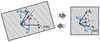
|
Figure 1
Pure shape deformation: relation of real (left) and auxiliary (right) spaces. |
The deformation induces a modified metric for the virtual lattice,

where A is the direct lattice basis matrix in the Euclidean frame. Since the reference metric tensor  , defined by equation (33), is symmetric positive-definite, any nonsingular affine transformation preserves this property, ensuring that the transformed metric tensor
 remains symmetric positive-definite. This guarantees the validity of the metric-tensor formalism under arbitrary nonsingular affine shape deformations. From this relation, an updated orthogonalization matrix
 can be obtained analogously to the Cholesky decomposition in equation (36).
Although the transformed metric tensor completely describes the intrinsic geometry of the virtual lattice, including its lengths, angles and directional scaling factors, it does not uniquely determine its orientation with respect to the reference frame. In particular, the rotational component of the affine transformation  is not preserved at the metric-tensor level, since rigid-body rotations leave the associated Gram matrix unchanged. Consequently, a pure rotation of the crystallite shape relative to the lattice may leave unaltered while still modifying the orientation of the corresponding basis vectors. To retain the full affine character of the transformation, including arbitrary rotations and combined stretch–rotation operations, the transformed basis

must therefore be considered together with the metric tensor. The transformed metric may then be expressed equivalently as

highlighting that represents only the metric component of the transformation, whereas additionally preserves the orientation information required to describe the transformed geometry. In the following, is used to derive directions and scaling factors in the virtual lattice, while is employed whenever their Cartesian representation is required.
From equations (36), (37) and (38), in this virtual setting the reciprocal-basis and Miller-index relations remain formally identical,

but are now evaluated with respect to the virtual lattice. The transformation also introduces a volume-scaling factor associated with the virtual lattice,
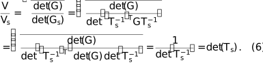
By reflecting the real-space shape deformation, this factor accounts for the change in geometric representation induced by the pull-back transformation and provides the volume-rescaling term required to consistently express the CVF relative to the reference shape.
Because the actual lattice is assumed to be unaltered, the original metric G is retained for crystallographic computations such as the evaluation of the Bragg peak positions (i.e. the interplanar spacing) according to equation (35), 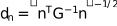 . The role of the virtual lattice is instead to provide the correct directions along which the Fourier coefficients of the shape transform must be evaluated. For a reflection
 , the direction normal to the corresponding
 planes in the virtual lattice is obtained from

The Cartesian representation of this direction in the virtual lattice is then obtained through the transformed basis as

thereby defining the direction along which the shape Fourier coefficients are evaluated. The normalized Miller indices commonly used in Fourier descriptions of simple polyhedral shapes [e.g. by Warren (1990) and Scardi & Leoni (2001)] are a consequence of the cubic metric implicitly assumed in the corresponding CVF formulations. In the present formalism, they are replaced by the normalized Cartesian components of the corresponding direction in the virtual lattice,

which ensures consistency between the transformed shape geometry and the directional dependence of its Fourier representation. This substitution preserves the geometric interpretation of the original shape equations while extending their applicability to arbitrary lattice metrics and affine shape transformations.
The cutoff distance at which the Fourier coefficients vanish, as well as the normalization length of the CVF  , are likewise rescaled by the deformation according to

where  represents the directional scaling induced by the pull-back transformation along the direction associated with the reflection n. The Fourier coefficients are then evaluated using the direction-dependent parameters
 derived from the virtual lattice, from which the corresponding coefficients
Hn and K are obtained. With these adjusted quantities, the standard analytical expressions for the Fourier coefficients of simple convex shapes [e.g. Scardi & Leoni (2001)] can be applied directly:

where L is the interatomic pair distance [or rather the `ghost' displacement length of Stokes & Wilson (1942)] and D is the characteristic dimension of the crystal domain (e.g. the sphere diameter). In this way, the deformation is accounted for through a directional rescaling of the characteristic lengths while preserving the known analytical CVF formulation.
Finally, the deformation modifies the volume of the finite crystal domain itself. The volume of the deformed domain is

where W and  denote the volumes of the reference and deformed crystallite domains, respectively. Since

 , the ratio
 corresponds to the volume scaling associated with the affine shape transformation. The volume scaling factor is required to preserve the relative diffraction contributions of distinct crystallite populations. This is particularly important in applications involving discrete size classes or shape distributions, where the integrated scattering contribution associated with each component depends on its physical volume. Accordingly, provides a consistent weighting factor that preserves the relative contribution of the deformed crystallite population within the total diffraction signal.
Notably, although different implementations of WPPM and WPDFM may account for volume normalization through different computational strategies, the explicit use of is particularly advantageous. Since the deformation tensor is intended to modify the crystallite shape rather than its characteristic size, variations in inevitably alter the crystallite volume through . Introducing as a normalization factor decouples this geometrically induced volume variation from the independent size parameters of the model, thereby enabling robust refinement of the shape-deformation parameters. In practice, this allows to be optimized to achieve the best agreement between modelled and observed X-ray PD patterns without introducing spurious correlations with the crystallite-size distribution parameters.
This virtual-lattice formalism provides a unified mechanism for incorporating arbitrary affine shape deformations into the modelling of the powder-diffraction profile, while preserving the crystallographic information carried by the physical lattice, including the lattice parameters and Bragg peak positions.
2.2.2. Crystal lattice deformation with fixed domain shape and size
In certain situations, the primary interest lies not in deforming the crystallite shape but in modelling modifications of the underlying lattice. Changes in lattice geometry can generate new reflections absent in the parent structure or eliminate others through symmetry enhancement. Such cases arise, for example, when modelling subtle distortions, phase transitions or size/shape effects in materials with intrinsically low symmetry. In these situations, one often wishes to preserve the external domain shape and volume while deforming only the lattice.
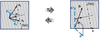
Let  denote the deformation applied to the lattice that maps the original structure onto the target one (Fig. 2). As an illustrative example, may transform a face-centred cubic lattice into a face-centred tetragonal one. The metric of the deformed lattice follows directly from this mapping:

where  is the orthogonalization matrix of the reference lattice and

is the corresponding orthogonalization matrix for the transformed lattice. Consistent with the extended treatment of shape deformations,  is constructed directly from rather than being obtained from a decomposition of
 , thereby retaining the full affine transformation, including relative orientation information. This metric must now be used consistently for all crystallographic calculations involving the transformed lattice, including coordinate transformations into orthonormal space,

and the evaluation of interplanar spacings. Unlike the shape-deformation case, the metric tensor replaces in all crystallographic calculations because the lattice itself is physically deformed. The metric-tensor expression of equation (35) remains formally unchanged, provided that the deformed metric tensor is used, 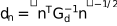 .
|
Figure 2
Pure lattice deformation: relation of real (left) and auxiliary (right) spaces. |
Analogously to the treatment of shape deformations, the same formalism can be used to determine the directions associated with reflections in the transformed lattice. For a reflection  , the direction normal to the corresponding planes in the transformed lattice is obtained from

The Cartesian representation of this direction is then obtained through the transformed basis as

thereby defining the corresponding direction in the deformed crystal structure. As in the case of the virtual lattice, the normalized Miller indices commonly used in Fourier descriptions of simple polyhedral shapes are replaced by the normalized Cartesian components of the corresponding direction,

This substitution preserves the geometric interpretation of the original shape equations while extending their applicability to arbitrary lattice metrics and affine lattice transformations.
Importantly, because the deformation affects only the lattice and not the crystal domain shape, neither the domain volume nor the cutoff position of the Fourier coefficients is altered relative to the standard expressions for the chosen shape. The Fourier treatment of size broadening therefore proceeds exactly as in the undeformed case. Nevertheless, the directions associated with a given reflection are modified through the transformed metric tensor , resulting in updated direction cosines  for the evaluation of the shape Fourier coefficients. The lattice deformation thus manifests itself through the modified metric, the altered reciprocal-lattice geometry, and the resulting changes in interplanar spacings, peak positions and potentially symmetry-dependent reflection conditions.
2.2.3. Coupled domain shape and crystal lattice deformations
In many practical situations, the deformation affecting a crystalline domain cannot be attributed solely to a change in shape or solely to a change in lattice geometry; rather, both effects occur simultaneously. The combined treatment of shape and lattice deformations enables the modelling of complex crystallite morphologies embedded within lattices of reduced symmetry, starting from a reference configuration of known shape and lattice geometry. To account for this general condition, the shape deformation tensor and the lattice deformation tensor are treated as distinct transformations acting on different components of the model. The former modifies the domain geometry through a pull-back operation, whereas the latter modifies the crystal lattice through a push-forward transformation. The resulting diffraction profile is therefore governed by the relative action of the two transformations.
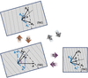
The lattice deformation modifies the metric of the underlying Bravais lattice according to  [i.e. equation (13)], while the shape deformation acts on the already transformed lattice through the pull-back operation associated with . The combined effect of the two transformations is therefore obtained by applying the lattice push-forward transformation followed by the shape pull-back transformation (Fig. 3). The resulting relative deformation operator is described by

and the metric associated with the transformed domain becomes (Appendix B)

As discussed for the pure shape and lattice deformation cases, the combined transformed basis

must be constructed directly from the combined transformation tensor in order to retain the full affine mapping, including rotational components that may not be uniquely recoverable from the metric tensor alone. The associated tensor can then be equivalently obtained as

These expressions highlight that the transformed geometry is controlled by the relative action of the lattice and shape deformation tensors. Consequently, both transformations must be considered when evaluating the geometric, crystallographic and reciprocal-space properties of the deformed crystal.
|
Figure 3
Coupled shape–lattice deformation: relation of real (top left) and auxiliary (bottom right) spaces through the intermediate pure lattice deformation (bottom left). |
For crystallographic quantities such as Bragg peak positions and interplanar spacings, only the lattice deformation contributes. Accordingly, these quantities are evaluated using the deformed lattice metric , independently of the shape transformation . The metric-tensor expression of equation (35) therefore remains valid as 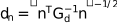 . However, for evaluating the Fourier coefficients associated with the finite crystallite shape, and thus the diffraction peak profile, the combined shape–lattice deformation must be considered explicitly. For a reflection
 , the direction normal to the corresponding planes in the coupled transformed configuration is obtained from

The Cartesian representation of this direction is then obtained through the combined transformed basis  as

thereby defining the direction along which the shape Fourier coefficients must be evaluated.
The normalized directional components entering the CVF formulation are therefore given by

and the cutoff distance at which the Fourier coefficients vanish, as well as the normalization length of the CVF, are likewise rescaled by the combined deformation according to

Here  represents the directional scaling induced by the combined action of the lattice deformation and the shape pull-back transformation along the direction associated with the reflection n.
Coupled shape and lattice deformations also affect both the virtual unit-cell volume and the volume of the crystallite domain. The transformed unit-cell volume obeys
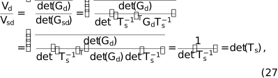
showing that the volume scaling associated with the combined transformation is determined solely by the shape deformation. Consequently, the volume of the transformed crystallite domain becomes

As in the pure shape-deformation case, this factor provides the appropriate normalization required to preserve the relative diffraction contributions of crystallite populations while separating shape effects from the independent size parameters of the model.
Together, these relations provide a complete and unified description of systems in which both lattice and shape deformations contribute to the diffraction signal, encompassing the most general conditions encountered in realistic nanostructured materials. The formalism treats lattice and shape deformations independently while preserving their coupled effects on the crystallographic and finite-domain contributions to diffraction. As a result, changes in reciprocal-space geometry, interplanar spacings, reflection directions and shape Fourier coefficients can be evaluated consistently within a single metric-tensor framework.
The relative deformation mapping  provides a direct measure of the mismatch between lattice and shape evolution. The pure shape and pure lattice deformation formalisms are recovered as limiting cases for
 and
 , respectively. A particularly important case occurs when
 , for which
 and the transformed geometry becomes equivalent to the reference configuration. In this limit, lattice and shape deform coherently, producing no relative distortion between the crystallographic and morphological descriptions. Deviations from this condition quantify the degree of decoupling between lattice and shape deformations, providing a natural framework for describing strain, morphology evolution and symmetry changes in complex crystalline systems.
From an implementation perspective, the proposed formalism acts as a preprocessing stage to conventional WPPM and WPDFM calculations. For a given set of shape and/or lattice deformation tensors, the transformed metrics, orthogonalization matrices, reflection directions, direction cosines, CVF coefficients, truncation lengths and associated normalization factors are first evaluated according to the relations derived above. These quantities can then be supplied directly to existing Fourier-coefficient and profile-calculation routines without modification of the underlying WPPM or WPDFM formalism.
2.3. Powder size distribution
A compact and efficient strategy for incorporating crystal size distributions into the diffraction model consists of averaging the Fourier coefficients directly over the size distribution, rather than integrating the full diffraction profiles (Scardi & Leoni, 2001). Following this approach, the Fourier coefficient for a direction  is computed as a volume-weighted average of the size-dependent coefficients
 :

where  corresponds to the directional Fourier coefficients derived from the finite-domain formalism summarized in Appendix C,
 is the size distribution and
 is the volume of a domain of characteristic size D. This formulation greatly reduces computational complexity because the integration is performed directly on the analytical expressions of the Fourier coefficients, bypassing the need to compute and average full diffraction patterns. Closed-form solutions of equation (29) exist for the most common probability distributions and domain shapes (Leoni, 2019; Leonardi et al., 2022; Scardi & Leoni, 2001).
The same strategy can be extended to deformed domains. However, a limitation arises because the integral in equation (29) applies naturally only to shapes described by a single size parameter. In the present framework, deformation generally produces crystallites characterized by three independent size parameters as well as a specific orientation of their principal axes with respect to the lattice vectors. Analytical averaging is still possible in certain cases, such as when one or more size ratios are fixed, but in the most general scenario, numerical integration is required. Despite this, the approach remains computationally efficient and provides a practical route for incorporating realistic size distributions into diffraction-profile modelling, even in the presence of complex coupled deformations.
2.4. Integrating shape and lattice deformation in reciprocal- and real-space total-scattering analysis
The formalism developed above can be incorporated directly into the WPPM framework, where the implementation is particularly straightforward. The expressions that we derived extend those already used in WPPM to compute peak profiles. Consistent with the Fourier-domain intensity formalism introduced in equation (46), the contribution to the diffraction signal associated with a direction  is written as

where the Fourier coefficients  and
 incorporate finite-size effects, domain shape and the combined shape–lattice deformation tensors. The full powder pattern is then obtained by summing all relevant directions, restricted in practice to those generating observable reflection peaks, with peak intensities either refined independently [e.g. Pawley, Le Bail methods (Le Bail et al., 1988; Pawley, 1981)] or constrained by a structural model [e.g. Rietveld method (Rietveld, 1967)]. In this way, the deformation tensors, virtual-lattice mapping and directional Fourier coefficients integrate seamlessly into WPPM without altering its core formulation.
Although WPPM provides the most direct reciprocal-space implementation, the same mathematical ingredients can be used to model real-space total-scattering signals. For the test cases presented hereinafter, we use the WPDFM method, which is the real-space counterpart of WPPM and provides a practical implementation pathway that naturally benefits from lattice deformation mappings and the identification of independent crystallographic directions in base lattices such as face centred, body centred and simple cubic. In this context, deformation tensors rescale or rotate the pair-distance grid used to evaluate the CVF or, more generally, the directional Fourier coefficients [equations (44) and (45)]. The corresponding expression for the intensity becomes

which is adapted from the Debye scattering equation (Leonardi & Bish, 2016; Debye, 1913). Importantly, incorporating shape and lattice deformation directly within the WPDFM framework ensures that all diffuse-scattering contributions, most notably the thermal diffuse scattering (Urban, 1975), are modified in a manner fully consistent with the deformed domain geometry.
The same formalism applies equally well to other real-space PDF-fitting strategies, including methods such as the interpolation method (Yurchenko et al., 2016; Yurchenko et al., 2015; Yurchenko, 2014). Within such approaches, the deformation tensors introduced here play the same role: they modify the sampling of pair distances and the orientation of crystallographically independent directions, while the underlying shape transform governs the decay and modulation of the PDF. Thus, whether implemented within a WPDFM-style workflow or a PDF-interpolation framework, the mathematical treatment of size, shape and lattice deformation is formally equivalent to that used in WPPM (Leonardi, 2021; Stokes & Wilson, 1942; Wilson, 1955). Whether applied in reciprocal space through WPPM or in real space through WPDFM or PDF-interpolation methods, the combined use of deformation tensors, virtual-lattice mapping and direction-dependent Fourier coefficients provides a unified and flexible strategy for modelling diffraction and total-scattering signals from domains exhibiting coupled shape and lattice distortions.
3. Results
To demonstrate the capabilities of the proposed formalism and to evaluate the accuracy of the modelling approach, virtual powder X-ray diffraction datasets were first generated using the Debye scattering equation (DSE) (Leonardi & Bish, 2016). These Debye-generated PD profiles are based on fully atomistic models with known shape and lattice deformation and therefore serve as surrogate experimental datasets. The resulting profiles were then analysed using the WPDFM framework extended by the theoretical derivations introduced in Section 2.2, which enables LPA accounting for coupled shape and lattice deformation. While the WPPM framework offers a direct reciprocal-space route, the WPDFM method is particularly advantageous for the present test cases because it handles detailed shape effects and is naturally compatible with the DSE formalism across both wide- and small-angle regimes. Within this framework, the deformation parameters were refined by simulated annealing, used solely as a numerical optimization strategy. The refined deformation parameters obtained from the analysis were finally compared with the nominal values used to construct the atomistic models, providing a direct validation of the proposed approach.
All benchmark simulations were performed using the face-centred cubic (f.c.c.) Pd structure (unit-cell parameter 0.389070 nm). For each test case, an ensemble of 100 nanocrystals with the desired shape, size and orientation was generated, with the lattice origin randomly placed within the unit cell to mimic the translational disorder expected in real powders (Minami & Ino, 1979). The powder-diffraction profiles were obtained by summing the individual DSE intensities of all nanocrystals in the ensemble. This procedure was applied to all simulated Pd test cases discussed below. The only exception is the final, most realistic example addressing the Cu–Pd solid-state phase transformation, where atomistic configurations were generated from molecular-dynamics (MD) simulations and the diffraction signal was computed directly from the MD snapshots (Leonardi et al., 2011; Brandstetter et al., 2008).
While the examples presented are based on cubic structures for ease of visualization, the proposed formalism is symmetry independent and applies equally to triclinic lattices. The affine transformations act on a general lattice basis and therefore require no additional theoretical developments for lower-symmetry crystal systems. Furthermore, the computational cost associated with the transformations is negligible compared with the calculation of the scattering profile itself and is not expected to increase with decreasing lattice symmetry.
3.1. Shape elongation
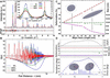
Spherical Pd nanocrystals with a 10 nm diameter were used as a root reference. Ellipsoids were generated by elongating the sphere along the [100] direction from 10 to 60 nm in increments of 5 nm (0–600% elongation). Representative diffraction profiles optimized by WPDFM modelling for the 0%, 250% and 500% elongation cases are shown in Fig. 4(A). Model refinement was carried out using simulated annealing, starting from parameters corresponding to an 8 nm Pd sphere. The WPDFM-based LPA of the Debye-simulated PD profiles follows the deformation state (i.e. case 4 in Table 1) and implements the Domain shape deformation with fixed lattice formalism introduced in Section 2.2.1, specifically using equations (9), (10), and (12).
|
Figure 4
Shape deformation: deformation states (A–C) and (D) . Modelling of powder-scattering data from powders of f.c.c. Pd ellipsoidal nanocrystals with constant volume (unit cell 0.389070 nm, crystal volume ∼524 nm3). (A) Comparison between DSE simulation (dots) and WPDFM modelling (lines), and (B) reduced pair distribution function (continuous lines) and small-angle shape function corrections (dot–dashed lines) for the ellipsoids elongated along [100] by 0%, 250% and 500%. (C) Ellipsoid axes and corresponding deformation obtained via WPDFM modelling of the profiles (symbols) are compared with expected values (black lines). (D) Difference in goodness of fit between refinements performed with optimized crystal shape–lattice relative orientation and with the ellipsoid principal axis constrained along [100] (top), together with the refined crystal size and longitudinal and transverse deformation parameters (middle), and the deviation of the elongation axis from the [100] direction (bottom). Parameters estimated via global optimization of the agreement between Debye-simulated and WPDFM-modelled profiles (symbols) are compared with the nominal values (black lines) for crystals whose principal axis follows the geodesic orientation path  on the unit sphere, connecting the high-symmetry crystallographic directions  ,  and  . |
As expected, increasing elongation modifies the decay envelope of the PDF, shifting its maximum toward shorter pair distances [Fig. 4(B)]. This behaviour reflects the intrinsic anisotropy introduced by shape deformation and highlights the inadequacy of assuming spherical particles when analysing PDF data of anisotropic nanoparticles. The WPDFM approach recovers the size and aspect ratio of the ellipsoids with negligible error relative to the DSE-generated profiles; residual differences diminish with increasing scattering momentum Q, due to the decay of the Pd atomic scattering factor. The refined ellipsoid axes and corresponding deformations closely reproduce the nominal values [Fig. 4(C)]. Minor discrepancies originate from the smooth approximation of the atomistic shape through the CVF. Equivalent accuracy is obtained for ellipsoids elongated along arbitrary crystallographic directions spanning the orientation space between the high-symmetry directions [100], [110] and [111].
We further extended the deformation state of case 4 (Table 1) from to , thereby completing the coverage of all cases belonging to group 4. A set of ellipsoids deformed by 25% and rotated was simulated along the conventional high-symmetry  path, following the standard crystallographic convention (Setyawan & Curtarolo, 2010), with Γ, K and M corresponding to the
 ,
 and
 directions, respectively. The refined sizes and directional parameters [Fig. 4(D)] exhibit excellent agreement. The orientation errors remain below 1% in the most challenging regions between [110] and [111], where shape-truncated pair distances vary only subtly across directions.
Here, spherical and ellipsoidal domains were deliberately selected for validation because they represent one of the most demanding test cases for the proposed formalism. Unlike faceted particles, such as cubes, tetrahedra or octahedra, ellipsoids do not produce characteristic oscillatory features arising from parallel facets in the diffraction profile. Consequently, the deformation must be recovered from comparatively subtle changes in the diffuse line profile alone. Demonstrating accurate refinement under these conditions provides a stringent validation of the generalized affine framework. For faceted morphologies, where shape-specific diffraction features are more pronounced, the expected discriminating power is correspondingly greater.
3.2. Lattice and shape relative misorientation
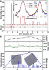
Cylindrical nanocrystals present additional modelling challenges due to the coexistence of curved surfaces, sharp edges and flat facets. Powder-diffraction patterns were simulated for monodisperse cylinders (base diameter = 10 nm, height = 10 nm) with their symmetry axis oriented along various directions relative to the f.c.c. base Cartesian system, following the geodesic orientation path connecting the high-symmetry directions [100], [110] and [111]. Representative DSE profiles and corresponding WPDFM fits for cylinders aligned along [100], [110] and [111] are shown in Fig. 5(A). The WPDFM-based LPA of the Debye-simulated PD profiles follows the deformation state  (i.e. case 2 in Table 1) and implements the Crystal lattice deformation with fixed domain shape and size formalism introduced in Section 2.2.2, specifically using equation (15).
|
Figure 5
Shape rotation relative to the lattice base: deformation state  . Modelling of powder-scattering data from powders of f.c.c. Pd cylindrical nanocrystals with height equal to the base diameter (unit cell 0.389070 nm and size 10 nm). (A) Scattering intensity profile from crystals with the cylinder axes along the [100], [110] and [111] crystallographic directions. The profiles modelled using the WPDFM method and shape rotation matrix (line) are compared with the average solution of the Debye scattering equation for a set of 100 equivalent crystals with a random position of the cylinder centre, relative to the lattice origin (dots). (B) Difference in goodness of fit between refinements performed with optimized crystal shape–lattice relative orientation and with the cylinder axis constrained along [100] (top), together with the refined crystal size (middle) and deviation of the cylinder axis from the [100] direction (bottom). Parameters estimated via global optimization of the agreement between Debye-simulated and WPDFM-modelled profiles (symbols) are compared with the nominal values (black lines) for crystals whose cylindrical axis follows the geodesic orientation path on the unit sphere, connecting the high-symmetry crystallographic directions , and . |
Among the reflections, the [111] peak is most sensitive to the orientation of the cylinder axis, and accordingly, this case shows the largest modelling deviations (Fig. 5). Nonetheless, parameter extraction remains robust, with size and orientation retrieved with negligible error. The angular dependence of model discrepancies mirrors that observed for ellipsoids, indicating that small variations in shape-truncated pair distances near the [110]–[111] manifold limit the discriminability of closely related orientations.
Although cylinders exhibit characteristic shape-dependent oscillatory features in their diffraction profiles, the information associated with crystal morphology is not restricted to these signatures. Shape anisotropy and relative shape–lattice orientation also influence the overall profile broadening and diffuse-scattering behaviour. Consequently, the successful refinement of the spherical and ellipsoidal test cases discussed in Section 3.1, where facet-induced oscillations are absent or weak, demonstrates that the proposed formalism does not rely solely on the presence of pronounced size fringes. The oscillatory features observed for cylinders therefore provide additional shape-sensitive information rather than the sole basis for parameter determination.
3.3. Shape deformation and misorientation relative to the lattice
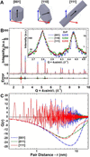
Unlike ellipsoids and cylinders, hexagonal prisms in an f.c.c. lattice have sharp edges and flat facets that introduce more complex, orientation-dependent peak shapes. Existing analytical shape functions cover only a limited subset of such geometries and do not explicitly incorporate orientation. To test the generality of the proposed framework, three families of nanoprisms were generated: (i) prisms with edge  nm and height
 nm oriented along [001], (ii) platelet-like prisms with
 oriented along [110], and (iii) rod-like prisms with
 oriented along [111]. The WPDFM-based LPA of the Debye-simulated PD profiles follows the deformation state
 (i.e. case 6 in Table 1) and implements the Coupled domain shape and crystal lattice deformations formalism introduced in Section 2.2.3, specifically using equations (25), (26) and (28).
Fig. 6 shows the particle shapes, the corresponding DSE powder patterns and the WPDFM modelling results. Differences in peak shapes, particularly the pointed peaks arising from sharp prism edges, are accurately reproduced. As expected, differences in the PDF at long distances [Fig. 6(C)] reflect the varying effective lengths of the prisms along different orientations. In real datasets, such shape-dependent effects are further moderated by noise and background contributions, which tend to homogenize residuals across peaks.
|
Figure 6
Combined deformation and rotation of the shape: deformation state . Modelling of powder-scattering data from powders of f.c.c. Pd nanocrystals with hexagonal prism shape and different longitudinal-to-transverse size–shape ratio (unit cell 0.389070 nm, size 16 nm). (A) Nanoprism with axes along the [100], [110] and [111] crystallographic directions with a size ratio 1:4 for the [110] platelet-like and 5:1 for the [111] rod-like shapes. (B) Scattering intensity profiles modelled using the WPDFM method and shape rotation matrix (lines) are compared with the average solution of the Debye scattering equation for a set of 100 equivalent crystals with random position of the shape relative to the lattice structure (dots). (C) Pair-distribution-function (continuous lines) and small-angle shape function corrections (dot–dashed lines). |
3.4. Lattice deformation
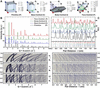
To demonstrate the impact of pure lattice deformation, primitive-cubic (P) Pd nanocrystals were transformed into base-centred (C), body-centred (I) or face-centred (F) lattices following the deformation paths illustrated in Fig. 7(A). The diffraction patterns of the fully deformed lattices [Fig. 7(B)] exhibit expected symmetry-driven changes: some reflections disappear due to systematic absence conditions, while others change intensity because of altered multiplicities and structure factor. The corresponding PDFs [Fig. 7(C)] show identical interatomic distances for base-centred and face-centred lattices but in different multiplicities, as expected from the number of centred faces. Both the intensity PD and PDF profiles were computed with the WPDFM method following the Crystal lattice deformation with fixed domain shape and size formalism introduced in Section 2.2.2, specifically using equation (18) to describe the deformation state  (i.e. case 1 in Table 1).
|
Figure 7
Deformation of the lattice: deformation state . Modelling of powder-scattering data from powders of Pd spherical nanocrystals with different lattice structures (size 10 nm). (A) Base-, body- and face-centred end-member structures obtained from the deformation of a cubic primitive unit cell (cell parameter 0.389070 nm). (B) and (C) Intensity profile and pair distribution function modelled for powders of spherical crystals with the end-member structures outlined in (A). (D–F) and (G–I) Respectively, intensity and pair-distance profile evolution with crystal structure varying between primitive (bottom) and deformation end members (top) according to the transformation paths drawn in (A) with the lattice deformations constrained to preserve the lattice parameter of the equivalent cubic end-member structure (see main text for a detailed description of the deformation paths). |
The transformation from a primitive (P) cell to the base-centred (C), body-centred (I) and face-centred (F) representations associated with the same cubic lattice (i.e. describing the same underlying cubic Bravais lattice with identical lattice parameters) can be described as a linear transformation of the basis vectors. By parameterizing the lattice deformation through a transformation fraction  , a continuous sequence of intermediate lattice states can be generated [Figs. 7(D)–7(F)]. This transformation involves both a rescaling of the basis vector lengths and a corresponding change in the interaxial angles. For example, the conversion from the primitive to the face-centred setting transforms the lattice parameters from a = 3.89070 Å with 90° interaxial angles to a = 2.75114 Å with 60° angles. The transformation can be expressed as a one-parameter family of linear mappings
 , , where
 is the basis transformation matrix corresponding to the target centred lattice. This formulation provides a continuous interpolation between the primitive cubic basis (
 ) and the primitive basis of the centred lattice (
 ). The end-member transformations are given by
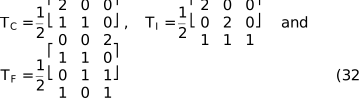
for base-centred ( ), body-centred (
 ) and face-centred (
 ), respectively.
The corresponding PDFs [Figs. 7(G)–7(I)] show a smooth evolution of interatomic separations and intensities, demonstrating that the deformation tensor framework naturally bridges symmetry-related structures along a continuous transformation path. Beyond its conceptual utility, this representation can also provide practical computational advantages. The affine transformations introduced in Section 2 are expressed through general matrix operations and are therefore independent of lattice symmetry, requiring no additional theoretical developments for lower-symmetry systems, including triclinic lattices. Their computational cost is negligible compared with the calculation of the scattering profile itself. In the context of WPDFM, the representation of centred lattices through appropriately deformed primitive lattices further reduces the complexity associated with explicit multi-site unit-cell descriptions (Leonardi, 2021). As a result, structures such as base-centred, body-centred and face-centred lattices can be treated with computational efficiency comparable to that of a primitive lattice while retaining an exact description of the underlying crystal structure.
3.5. Simultaneous shape and lattice deformation
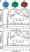
Simultaneous deformation of the lattice and particle shape was tested by modelling the Bain path linking f.c.c. Pd to its metastable b.c.t.10-like configuration [Fig. 8(A)]. Along this path, the reduction of the
c/a ratio modifies both the lattice metric and the crystallite morphology: spheres transform into ellipsoids, cubes into parallelepipeds and so on. The WPDFM-based LPA of the Debye-simulated PD profiles follows the deformation state  (i.e. case 5 in Table 1) and implements the Coupled domain shape and crystal lattice deformations formalism introduced in Section 2.2.3, specifically equations (25), (26) and (28).
|
Figure 8
Coupled lattice and shape deformations. Modelling of powder-scattering data from powders of Pd nanocrystals along the Bain (1924 ) deformation path (unit cell 0.389070 nm, size 10 nm). (A) F.c.c. nanocube deforms to the metastable body-centred tetragonal (b.c.t.10) structure through the body-centred cubic (b.c.c.) end member. (B) Scattering intensity profiles modelled using the WPDFM method and lattice deformation matrix only (lines) are compared with the average solution of the Debye scattering equation for a set of 100 equivalent crystals with random position of the shape relative to the lattice (dots). (C) Scattering intensity profiles modelled using the WPDFM method and both lattice and shape deformation tensors (lines) are compared with the average solution of the Debye scattering equation for a set of 100 equivalent crystals with random position of the shape relative to the lattice (dots). The independent global optimization of the Debye profiles modelled with the WPDFM from an f.c.c. 8 nm cubic crystal yielded the estimation of the true parameters with an error of <0.5% and goodness of fit of <0.01. |
Using only lattice deformation [Fig. 8(B)] captures the first-order peak-position changes but fails to reproduce subtle modulations, such as the intensity ripples associated with finite crystal dimensions. Incorporating both lattice and shape deformation [Fig. 8(C)] yields markedly improved agreement, especially in these ripple regions. The corresponding difference plots become nearly featureless, emphasizing the necessity of including both deformation modes to model diffraction profiles accurately. This combined-tensor strategy generalizes to any solid-state phase transformation, linking peak-shape evolution directly to the underlying changes in lattice geometry.
3.6. Phase-transition-induced shape deformation in a solid–solid phase transformation
The solid–solid phase-transition-driven shape evolution of Cu–Pd nanocrystals during thermal annealing provides an ideal test case for assessing the importance of explicitly including shape and lattice deformation in diffraction-profile modelling. In this system, the phase transformation from the disordered f.c.c. A1 random alloy to the ordered b.c.c. B2 intermetallic phase is accompanied by a measurable and systematic deformation of particle shape across the ensemble. This makes it possible to extract both the lattice deformation and the induced shape deformation directly from the diffraction signal. The crystallite-size distribution is first determined reliably in the A1 state; the subsequent deformation occurring during the A1→B2 phase transformation can then be refined directly from the PD profiles or imposed as a physically motivated constraint to stabilize the refinement of thermal and mechanical disorder parameters.
To isolate shape-evolution effects from other microstructural processes, such as coalescence, grain growth or melting, classical MD simulations were employed as a controlled surrogate for real experimental samples. Spherical nanocrystals with sizes ranging from 10 to 30 nm were equilibrated at room temperature. In the A1 phase, Cu and Pd atoms were distributed randomly, whereas in the B2 phase, atoms were arranged according to ideal intermetallic ordering. Debye-scattering powder profiles were then generated from the final equilibrium MD snapshots, naturally incorporating thermal (dynamic) disorder together with static and mechanical distortions such as surface relaxation. Although these MD–Debye profiles do not reproduce all complexities encountered in experimental measurements, including instrumental broadening, background contributions, counting statistics, preferred orientation and other sample-dependent effects, they provide a controlled validation environment in which the underlying structure and deformation state are known exactly. Importantly, each nanocrystal was equilibrated independently and subsequently used directly for the Debye-scattering calculations. As a result, every particle developed its own size-dependent deformation state, including deviations from the ideal lattice and departures from the nominal spherical morphology. These distortions were neither prescribed nor constrained during model generation, but emerged spontaneously during equilibration from the underlying interatomic interactions. The diffraction profiles analysed below therefore probe realistic coupled shape–lattice distortions whose magnitude and character are determined directly by the atomistic dynamics rather than by construction.
For the present purpose, namely assessing the ability of the proposed formalism to recover crystal shape and lattice deformation from diffraction data, the omission of experimental artefacts is not expected to affect the conclusions qualitatively. Instrumental- and sample-environment contributions can generally be minimized, characterized independently or corrected through established high-resolution diffraction and total-scattering methodologies (Solla-Gullon et al., 2015; Scardi et al., 2015). In particular, instrumental broadening can be made negligible relative to nanoscale size and strain broadening, while calibration errors, background contributions and preferred-orientation effects can be determined or reduced independently of the structural model. The use of MD-generated structures therefore allows the shape and lattice deformation problem to be examined in isolation from these experimental factors while retaining thermally and structurally realistic atomic configurations. This provides a stringent validation of the theoretical framework under conditions where the reference structure and deformation state are known exactly, something that is generally not attainable using experimental datasets alone.
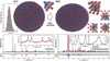
During MD equilibration, the f.c.c. intermetallic phase progressively develops a B2-like ordering (see Table 3) accompanied by a change in particle shape from spherical to ellipsoidal. Representative configurations and corresponding PD intensity profiles are shown in Fig. 9. Although the final configurations display the expected B2-type ordering and are free of crystallographic defects (dislocations, stacking faults, twins etc.), they also exhibit systematic periodic displacements from ideal b.c.c. positions, producing a Bragg peak sequence consistent with an array of eight B2-like building blocks forming a primitive orthorhombic supercell. This requires a fourfold enlargement of the conventional A1 f.c.c. cell to fully describe the resulting symmetry reduction.
|
||||||||||||||||||||||||||||||||||||||||||||||||||||||||||||||||||||||||||||||||||||||||||||
|
Figure 9
Modelling and LPA of the Cu–Pd random-alloy (A1) to intermetallic (B2) phase transformation. MD equilibrium configurations were generated to reproduce the powder-scattering signatures of the two end members of the thermal-annealing pathway in polydisperse Cu–Pd nanocrystal powders (Wang et al., 2016 ). Virtual-experiment diffraction profiles were computed as weighted sums of intensities obtained from the solution of the Debye scattering equation for spherical MD crystals with sizes ranging from 10 to 30 nm with lognormal frequency. The resulting synthetic profiles were analysed using the WPDFM framework. The intensity profile from the intermetallic (B2) case was analysed with alternative model assumptions on the crystal shape to assess the significance of accounting for the structure-dependent deformation. The model's parameters optimized via simulated annealing are listed in Table 4. |
The MD–Debye PD profiles were analysed using the WPDFM framework, refining lattice parameters, size distributions, thermal disorder [modelled via an isotropic Debye–Waller factor ( ) with short-range correlation length
 ], mechanical disorder [Wilkens–Krivoglaz model (Wilkens, 1970; Wilkens, 1969)] and B2-phase shape-deformation modes (elongation and shear). The size distributions refined from the A1 profiles agree closely with the nominal lognormal distribution used to generate the MD ensemble. Discrepancies arise because the approximation in the isotropic lattice distortion (BuILD) thermal model (Leonardi & Leoni, 2023). The diffuse scattering of the random alloy cannot be fully captured by a single-site-type isotropic thermal model [i.e.
 and
 ]; in the A1 state, Cu and Pd atoms occupy equivalent crystallographic sites but possess different phonon spectra, which the mixed-site isotropic thermal model cannot discriminate. Using an anisotropic thermal model improves the agreement but does not fully eliminate the mismatch, confirming that the thermal model, not the size-distribution extraction, is the principal limiting factor in the A1 case. In contrast, modelling of the ordered B2-like phase is less affected by this limitation. Because Cu and Pd occupy distinct crystallographic sites, their differing vibrational behaviour, and thus their distinct phonon structures, are captured naturally by the thermal model and the independent
 and
 values. As a result, the agreement between the MD–Debye patterns and the WPDFM refinement is markedly improved for the B2-like structures. Crucially, the WPDFM implementation incorporates thermal diffuse scattering (TDS) implicitly through the short-range correlation length in the thermal disorder model. Consequently, no additional or dedicated TDS model is required when the particle shape deforms; the TDS contribution automatically adjusts to the deformed shape through the combined directional Fourier formalism.
The B2-like phase was refined using the size distribution extracted from the A1 state. Two strategies were compared: (i) assuming spherical particles, and (ii) allowing ellipsoidal particles with either constrained (f.c.c.→b.c.c.-like) or freely optimized aspect ratios and shear deformation (Table 4). Allowing for shape deformation improves the goodness of fit and  by ∼10% relative to the spherical assumption (Rietveld, 1969). Visual inspection shows that the elliptically deformed model reproduces peak intensities, especially peak maxima, far more accurately than the spherical model, while only marginally altering peak-broadening characteristics.
|



The freely refined aspect ratio and shear parameters of the ellipsoids are consistent with those expected from the orthorhombic distortion of the B2-like supercell, demonstrating that even modest shape deformations can be reliably extracted from the diffraction data. Moreover, refining the aspect ratio improves the estimation of the thermal short-range correlation length, bringing it closer to the value obtained for the A1 state. The mechanical disorder parameters remain broadly consistent across models, though the ellipsoidal particles show a slightly higher effective dislocation density, which is consistent with the enhanced static/mechanical disorder expected when increased surface-to-volume ratios amplify surface-relaxation effects. Consistent with experimental observations reported in the literature (Scardi & Gelisio, 2016; Gelisio et al., 2013; Scardi et al., 2015), the lattice distortion arising from bond relaxation at the free surfaces of nanocrystals is best described, within the Wilkens–Krivoglaz formalism, by edge-type dislocations. Indeed, as reported in Table 4, a mixing coefficient close to unity signifies that the anisotropic strain field is almost entirely associated with edge dislocation character, rather than a mixed or screw-type contribution, which corresponds to a mixing coefficient of zero. Interestingly, the degradation in goodness of fit associated with constraining the shape–lattice orientation is of comparable magnitude in both the idealized ellipsoidal benchmark cases [Fig. 4(D)] and the atomistic MD-derived Cu–Pd systems (Table 4). This observation indicates that the sensitivity of the diffraction profile to the relative shape–lattice orientation is retained even in structurally complex systems, suggesting that the effect should remain observable beyond the idealized validation cases considered here. This is consistent with the well established observation that size, strain and other microstructural contributions affect diffraction profiles in distinct ways, providing the basis for line-profile analysis methodologies such as Williamson–Hall, Warren–Averbach and WPPM (Leoni, 2019; Williamson & Hall, 1953; Warren & Averbach, 1950; Warren & Averbach, 1952).
To assess the feasibility of extracting deformation parameters under realistic experimental conditions, synthetic Gaussian noise was added to the virtual Debye profiles, with a standard deviation proportional to  , mimicking counting statistics. The noisy profiles were then refined with all deformation parameters allowed to vary freely. The results (Table 5) show only minimal deviations compared with the optimization of the noise-free datasets (Table 4). Although the introduction of noise leads to an expected increase in the fit residuals, with larger noise levels yielding higher overall errors, the refined structural parameters remain largely stable, with noticeable variations occurring only at the highest noise amplitudes. Importantly, the shape deformation coefficients exhibit weak sensitivity to noise, confirming the robustness of their extraction under conditions representative of real experimental data. Other instrumental aberrations can be effectively mitigated through appropriate experimental design and data treatment. For instance, statistical noise can be reduced by employing sufficiently long exposure times, while instrumental broadening can be minimized using high-resolution powder-diffraction beamlines at synchrotron sources, where it can often be considered negligible relative to the data collection step size. Similarly, background contributions arising from the sample environment or holder can be reliably removed through careful instrumental calibration procedures, as routinely performed in PDF experiments (Billinge & Farrow, 2013; Egami & Billinge, 2003).
|
 .


A common outcome of all refinements is that the effective dislocation radius  is comparable to or smaller than the minimum crystallite size present in the size distribution. This behaviour can be rationalized by noting that the same distortion model is applied uniformly across the entire ensemble of particles. When is smaller than the crystallite dimensions, the edge-dislocation model retains physical meaning and ensures a finite elastic energy integrated over the crystal volume. In contrast, the values of exceeding the smallest particle size would imply that the strain field does not relax as the dislocation approaches the surface of the smaller crystallites, leading to an unphysical description of the distortion. Notably, when the transformation matrix is refined without constraints, the rotational components are non-zero (see Appendix B for details). In particular, the
T23 term, although relatively small in magnitude, is responsible for a tilt of the c axis of approximately 15° with respect to the Cartesian reference frame of the parent structure base unit cell. In contrast, the combined effect of all off-diagonal components produces additional rotations of the a and b axes within the basal plane that do not exceed about 2°.
While the in-plane rotations are marginal, the pronounced tilt of the c axis clearly illustrates the advantage of the methodology we introduced. Indeed, detecting such a shape-deformation tilt would be extremely challenging using TEM alone, as well as other currently available PD LPA methods, underscoring the sensitivity of the diffraction-based approach. Overall, this realistic example demonstrates that explicitly accounting for shape deformation is essential to correctly interpret diffraction signals across solid–solid phase transformations. By enabling coupled refinement of lattice distortion, shape evolution, thermal disorder and mechanical strain, the proposed framework provides a robust route for analysing real nanostructured materials undergoing structural transitions.
4. Conclusions
In this work, we examined the effects of general linear transformations, including deformation and rotation, applied independently or jointly to both the lattice and the external shape of crystalline domains. Building on these concepts, we introduced a unified formalism based on the construction of a virtual lattice, which allows known analytical Fourier coefficients of undeformed reference shapes to be retained while consistently mapping arbitrary shape and lattice transformations into reciprocal space. This strategy enables the treatment of general domain geometries with arbitrary orientation relative to the crystal lattice, without requiring the derivation of new analytical shape functions for each specific deformation scenario.
The proposed formalism greatly expands the modelling capabilities of existing, well established tools for powder-diffraction LPA, such as TOPAS (Coelho, 2018), by lifting the traditional constraints imposed by a priori predefined CVFs. By enabling the dynamic deformation of the crystalline domain shape and/or the underlying lattice, the approach allows both effects to be treated as active and refinable degrees of freedom. Most notably, it enables the refinement of the relative orientation between shape and structure bases, a capability that was previously inaccessible within conventional line-profile modelling frameworks.
We demonstrated that this formalism integrates naturally within established powder-diffraction modelling strategies in both reciprocal and real space, including advanced line-profile and total-scattering approaches. The resulting diffraction and PDF profiles faithfully reproduce the combined effects of size anisotropy, lattice distortion and coupled shape–lattice transformations across a wide range of nanocrystal morphologies. A key aspect of the virtual-lattice construction is that a single deformation tensor governs both Bragg and diffuse-scattering contributions, including thermal diffuse scattering, ensuring internal consistency without the introduction of additional ad hoc modelling terms.
Using independently generated atomistic diffraction patterns as ground-truth benchmarks, we demonstrated that the proposed methodology allows deformation parameters to be retrieved reliably from powder-diffraction data alone. Even in cases where simplified thermal or mechanical distortion models limit a full description of the total-scattering signal, such as in random alloys where species-dependent phonon spectra cannot be resolved with currently available models, the extraction of shape and lattice deformation remains robust. For ordered intermetallic structures, where atomic species occupy distinct crystallographic sites, the framework captures the coupled evolution of shape and lattice with high fidelity. In this context, we show that while in-plane rotations of the particle axes are relatively small, a pronounced tilt of the axis can be resolved unambiguously. Detecting such a shape-induced tilt would be extremely challenging using TEM alone, as well as with currently available PD–LPA methods that rely on predefined shape models and fixed shape–lattice orientation assumptions. This result highlights the sensitivity of the diffraction-based approach introduced here and its ability to resolve deformation features that were previously inaccessible to ensemble-averaged techniques.
The present validation has been performed using diffraction patterns derived from independently equilibrated atomistic models, allowing direct comparison with structures whose underlying deformation state is known explicitly from the equilibrated atomic configuration. This provides a particularly stringent assessment of the correctness and robustness of the proposed formalism while avoiding the unavoidable uncertainty associated with experimental datasets for which the underlying deformation state cannot be established independently. Unlike experimental datasets, the atomistic benchmark enables direct quantitative assessment of parameter recovery because the reference solution is known. Importantly, the MD-derived diffraction patterns are not generated using the same analytical formalism employed during refinement but originate from independently equilibrated atomistic structures that naturally develop coupled shape and lattice distortions through thermal relaxation and interatomic interactions. Although application to experimental diffraction datasets would provide a valuable demonstration of practical applicability and represents an important avenue for future work, the results presented here establish the validity and generality of the affine-deformation framework itself.
Beyond the simultaneous refinement of shape and lattice deformation demonstrated in this work, the proposed framework provides a general extension of Fourier/CVF-based diffraction modelling to arbitrary affine shape transformations and shape–lattice relationships. In many practical situations, part of the relevant information may already be available from complementary techniques such as electron microscopy. For example, particle morphology and aspect ratio may be known, while the crystallographic growth direction, the relative shape–lattice orientation, or a deformation state associated with growth or phase transformation remain unknown. In such cases, the present framework allows the known information to be incorporated as a physically meaningful constraint while refining the remaining structural degrees of freedom from diffraction data. More generally, the approach enables the treatment of a wider range of anisotropic morphologies, including nanorods, nanowires, plate-like crystals, layered double hydroxides, clays, layered materials and systems undergoing shape-preserving phase transformations, without requiring shape-specific analytical derivations.
Taken together, these results establish a general and flexible affine-deformation framework for modelling diffraction profiles from realistic nanostructured materials, explicitly treating domain shape and lattice as independent yet coupled degrees of freedom. By enabling deformation-aware analysis without imposing crystallographic constraints on external morphology, this framework substantially extends the interpretive power of powder-diffraction and total-scattering methods. The approach opens the door to more accurate size-, shape-, orientation- and deformation-resolved studies of nanocrystals, with direct relevance for investigating phase transformations, strain-driven distortions, anisotropic growth, morphology evolution and crystallographic growth relationships in functional nanomaterials.
5. Supplementary information
An Excel workbook is provided as supplementary material to demonstrate the methodology described in this manuscript. The workbook was developed independently from the research software used in the reported applications and is intended for illustrative purposes only. It has not been extensively tested or validated and may contain errors or inaccuracies.
APPENDIX A
Tensor matrix
A given Bravais lattice  with basis
 is described by the metric tensor

such that

where V is the volume of the unit cell. Then, a column vector  describes in the reciprocal space the normal direction to a given crystallographic plane (hkl). The corresponding interplanar spacing is
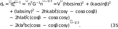
The Cholesky decomposition of the metric tensor  provides the matrix
 ,


which allows the representation in orthogonal coordinates  of a given vector n in reciprocal space:

APPENDIX B
Deformation tensors
Deformations of a body are most generally described using second-rank tensors. A triaxial deformation, incorporating simultaneous changes in length, shape and orientation, is represented by the deformation tensor, which in its general form can be written as

We can diagonalize to find the principal axes, i.e. the directions in which the deformation does not cause any shear. This corresponds to finding the eigen-decomposition:

From a computational standpoint,
Tx,
Ty and
Tz correspond to the eigenvalues of , while the columns of  are the associated eigenvectors.
The matrix represents the rotation that must be applied to the fixed reference frame to align it with the principal axes of the deformation. This rotation can equivalently be parametrized using three Euler angles  , expressed as the product of the corresponding elementary Euler rotation matrices about three independent axes. Introducing the matrices that describe a rotation by a generic angle
 about the
 and
 axes of the fixed frame, we write
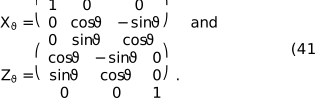
Considering the customary Euler sequence consisting of three successive rotations about the fixed frame , and axes by the angles  ,
 and
 , respectively, the resulting rotation matrix is obtained as
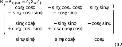
where  . Rotations are defined as active extrinsic Euler rotations in a right-handed orthonormal reference frame, applied successively about the fixed
 ,
 and
 axes. Using this rotation matrix, the full deformation tensor can be constructed bottom-up from the specified deformation parameters and rotation angles. This provides a convenient way to generate a deformed geometry, such as a distorted lattice or reshaped domain, and subsequently orient it relative to the initial reference frame.
APPENDIX C
Powder-diffraction profile modelling
Excluding defects and strain, each domain in a powder of a monoatomic material can be regarded as a finite portion of an infinite Bravais lattice. The underlying ideal lattice can be expressed as the Dirac comb:
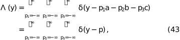
where  . A finite crystalline domain of shape
 is obtained by selecting the lattice points lying within the region . This is achieved by clipping the infinite lattice with the characteristic indicator function

To construct the real-space density of the finite crystallite, the clipped lattice is populated with a single-atom density  , typically the electron density for X-ray scattering or nuclear cross-section for neutrons. The density
 of the domain with shape is then generated by populating the clipped lattice via convolution:

This expression ensures that the resulting density is atomistically discrete yet preserves the smooth shape termination imposed by  , which in turn guarantees charge neutrality and continuity at the crystal surface (Ino & Minami, 1979). These properties explain the high accuracy of Fourier-based LPA compared with more traditional approaches that impose shapes directly in reciprocal space.
The amplitude,  , and intensity,
 , are obtained from the Fourier transform of the domain density:

where  is the Fourier operator and
 the reciprocal-space coordinates, i.e. the scattering momentum. Applying the convolution theorem yields

in which  is the atomic scattering factor [or nuclear scattering length for neutrons,
 ],

is the reciprocal-lattice Dirac comb with basis  and lattice node vectors
 and
 is the Fourier transform of the domain's shape characteristic indicator function. Then equation (47) becomes

In other words,  is the shape transform, which determines the peak profile around each reciprocal-lattice point.
Because only the neighbourhood of each reciprocal-lattice point contributes to the powder pattern, it is convenient to evaluate the shape transform along the radial direction  and write
 , which corresponds geometrically to counting scattering pairs at separation L along (Leonardi, 2021; Leonardi et al., 2013). In the Stokes–Wilson `ghost' construction,
 equals the common volume between the object and a copy shifted by
 (Leonardi et al., 2012; Wilson, 1962; Stokes & Wilson, 1942; Leoni, 2019; Scardi & Leoni, 2001). For mono-parametric shapes of size
 this yields a real function expressible as

and zero beyond the directional cutoff  . The coefficients
 and the cutoff
 depend on both the crystallite shape and the direction of observation (Scardi & Leoni, 2001).
The powder-diffraction pattern is finally constructed by averaging the three-dimensional intensity over the surface of the sphere
Sr where  as

For a perfect lattice, this spherical average reduces to a sum over symmetry-equivalent directions, providing an efficient route to the one-dimensional powder profile. Physically, the reciprocal lattice dictates where scattering occurs, while the atomic density sets the intensities and the crystallite shape determines the peak profile via  .
In practical computations, the averaging is often carried out using the tangent-plane approximation, which treats the integration sphere locally as flat. This approximation accelerates calculation and is accurate for narrow features in reciprocal space (large crystalline domains), but becomes progressively less valid for broader features (small crystalline domains). As a rough example, for crystallites of 10 nm diameter, the tangent-plane approximation introduces an error in peak width of less than 2% for Q > 2 Å−1, but can reach 8% in the small-angle region (Q < 1 Å−1). As expected, some differences appear at small diffraction angles where the radius of the integration sphere is small (Scardi et al., 2011), especially for complex-shaped domains. These considerations motivate the directional formulation above, where the primary contribution arises along , and the accuracy of the diffraction modelling depends on an appropriate representation of the shape transform in that direction.
Supporting information
Acknowledgements
Saudi Aramco is acknowledged for the continuous support and for the permission to publish this manuscript. Open access funding enabled and organized by Projekt DEAL.
Conflict of interest
The authors declare no conflicts of interest. The funders had no role in the design of the study; in the collection, analyses or interpretation of data; in the writing of the manuscript; or in the decision to publish the results.
Data availability
The original contributions presented in this study are included in the article/supplementary material. Further inquiries can be directed to the corresponding authors.
Funding information
The following funding is acknowledged: Deutsche Forschungsgemeinschaft (grant No. LE4543/2-1 to Alberto Leonardi). This research was supported in part by Lilly Endowment Inc., through its support for the Indiana University Pervasive Technology Institute.
References
 Allegra, G. & Wilson, A. J. C. (1983). Acta Cryst. A39, 280–282.
CrossRef
CAS
Web of Science
IUCr Journals
Google Scholar
Aviles, K. M. & Lear, B. J. (2025). ACS Nanosci. Au 5, 117–127.
CrossRef
CAS
PubMed
Google Scholar
Bain, E. C. (1924). Trans. Am. Inst. Min. Metall. Eng. 70, 25–46.
Google Scholar
Balić Žunić, T. & Dohrup, J. (1999). Powder Diffr. 14, 203–207.
Google Scholar
Billinge, S. J. L. & Farrow, C. L. (2013). J. Phys. Condens. Matter 25, 454202.
Web of Science
CrossRef
PubMed
Google Scholar
Boukouvala, C., Daniel, J. & Ringe, E. (2021). Nano Converg. 8, 26.
CrossRef
PubMed
Google Scholar
Brandstetter, S., Derlet, P. M., Van Petegem, S. & Van Swygenhoven, H. (2008). Acta Mater. 56, 165–176.
Web of Science
CrossRef
CAS
Google Scholar
Cho, M. G., Sytwu, K., Rangel DaCosta, L., Groschner, C., Oh, M. H. & Scott, M. C. (2024). ACS Nano 18, 29736–29747.
CrossRef
CAS
PubMed
Google Scholar
Coelho, A. A. (2018). J. Appl. Cryst. 51, 210–218.
Web of Science
CrossRef
CAS
IUCr Journals
Google Scholar
Crisp, R. W. & Singh, S. (2024). Cryst. Growth Des. 24, 7739–7741.
CrossRef
CAS
Google Scholar
Debye, P. (1913). Annal. Phys. 348, 49–92.
CrossRef
Google Scholar
Debye, P. (1915). Nachr. Koenigl. Ges. Wiss. Goettingen Math. Phys. Kl. 1915, 70–76.
Google Scholar
Du, C. X., van Anders, G., Newman, R. S. & Glotzer, S. C. (2017). Proc. Natl Acad. Sci. 114, E3892–E3899.
CAS
PubMed
Google Scholar
Ectors, D., Goetz-Neunhoeffer, F. & Neubauer, J. (2015). J. Appl. Cryst. 48, 189–194.
Web of Science
CrossRef
CAS
IUCr Journals
Google Scholar
Egami, T. & Billinge, S. J. L. (2003). Undeneath the Bragg Peaks. Structural Analysis of Complex Materials. Elsevier.
Google Scholar
Farrow, C. L., Juhas, P., Liu, J. W., Bryndin, D., Božin, E. S., Bloch, J., Proffen, T. & Billinge, S. J. L. (2007). J. Phys. Condens. Matter 19, 335219.
Web of Science
CrossRef
PubMed
Google Scholar
Fichthorn, K. A. & Yan, T. (2021). J. Phys. Chem. C 125, 3668–3679.
CrossRef
CAS
Google Scholar
Gelisio, L., Beyerlein, K. R. & Scardi, P. (2013). Thin Solid Films 530, 35–39.
CrossRef
CAS
Google Scholar
Giacovazzo, C. (2011). Fundamentals of Crystallography. Oxford University Press.
Google Scholar
Ino, T. & Minami, N. (1979). Acta Cryst. A35, 163–170.
CrossRef
CAS
IUCr Journals
Web of Science
Google Scholar
Khorsand Zak, A. & Hashim, A. M. (2025). Sci. Rep. 16, 1717.
CrossRef
PubMed
Google Scholar
Krawitz, A. D. (2001). Introduction to Diffraction in Materials, Science, and Engineering. John Wiley.
Google Scholar
Le Bail, A., Duroy, H. & Fourquet, J. L. (1988). Mater. Res. Bull. 23, 447–452.
CrossRef
ICSD
CAS
Web of Science
Google Scholar
Leonardi, A. (2021). IUCrJ 8, 257–269.
CrossRef
CAS
PubMed
IUCr Journals
Google Scholar
Leonardi, A., Beyerlein, K. R., Xu, T., Li, M., Leoni, M. & Scardi, P. (2011). Z. Kristallogr. Proc. 1, 37–42.
Google Scholar
Leonardi, A. & Bish, D. L. (2016). J. Appl. Cryst. 49, 1593–1608.
Web of Science
CrossRef
CAS
IUCr Journals
Google Scholar
Leonardi, A. & Leoni, M. (2023). Acta Mater. 243, 118491.
CrossRef
Google Scholar
Leonardi, A., Leoni, M. & Scardi, P. (2013). J. Appl. Cryst. 46, 63–75.
Web of Science
CrossRef
CAS
IUCr Journals
Google Scholar
Leonardi, A., Leoni, M., Siboni, S. & Scardi, P. (2012). J. Appl. Cryst. 45, 1162–1172.
Web of Science
CrossRef
CAS
IUCr Journals
Google Scholar
Leonardi, A., Neder, R. & Engel, M. (2022). J. Appl. Cryst. 55, 329–339.
Web of Science
CrossRef
CAS
IUCr Journals
Google Scholar
Leoni, M. (2014). TOPAS 5 Technical Reference, User Manual, p. 73. Bruker AXS GmbH.
Google Scholar
Leoni, M. (2019). International Tables for Crystallography, Vol. H, pp. 524–537. Wiley.
Google Scholar
Leoni, M., Confente, T. & Scardi, P. (2006). Z. Kristallogr. Suppl. 2006, 249–254.
CrossRef
Google Scholar
Li, C., Clament Sagaya Selvam, N. & Fang, J. (2023). Nanomicro Lett. 15, 83.
PubMed
Google Scholar
Loopstra, B. O. & Rietveld, H. M. (1969). Acta Cryst. B25, 787–791.
CrossRef
ICSD
IUCr Journals
Web of Science
Google Scholar
Marks, L. D. & Peng, L. (2016). J. Phys. Condens. Matter 28, 053001.
CrossRef
PubMed
Google Scholar
Minami, N. & Ino, T. (1979). Acta Cryst. A35, 171–176.
CrossRef
CAS
IUCr Journals
Web of Science
Google Scholar
Mohan, A. C., Athira, A., Nair, B. P., Sivasubramanian, G., Sreekanth, K. M., Anoop, G., Sree, S. P. & Sreedhar, K. M. (2024). Sci. Rep. 14, 32067.
CrossRef
PubMed
Google Scholar
National Science Foundation (2024). Tiny Crystals, Huge Impact – NSF Launches New Nanocrystals Research Center, https://www.nsf.gov/mps/updates/tiny-crystals-huge-impact-nsf-launches-new-nanocrystals.
Google Scholar
Neumann, S. & Rafaja, D. (2024). Powders 3, 531–549.
CrossRef
Google Scholar
Nguyen, Q. N., Chen, R. & Xia, Y. (2023). Trends Chem. 5, 748–762.
CrossRef
CAS
Google Scholar
Pawley, G. S. (1981). J. Appl. Cryst. 14, 357–361.
CrossRef
CAS
Web of Science
IUCr Journals
Google Scholar
Popa, N. C. (1998). J. Appl. Cryst. 31, 176–180.
Web of Science
CrossRef
CAS
IUCr Journals
Google Scholar
Rietveld, H. M. (1967). Acta Cryst. 22, 151–152.
CrossRef
CAS
IUCr Journals
Web of Science
Google Scholar
Rietveld, H. M. (1969). J. Appl. Cryst. 2, 65–71.
CrossRef
CAS
IUCr Journals
Web of Science
Google Scholar
Scardi, P. (2020). Cryst. Growth Des. 20, 6903–6916.
Web of Science
CrossRef
CAS
Google Scholar
Scardi, P., Azanza Ricardo, C. L., Perez-Demydenko, C. & Coelho, A. A. (2018). J. Appl. Cryst. 51, 1752–1765.
Web of Science
CrossRef
CAS
IUCr Journals
Google Scholar
Scardi, P. & Gelisio, L. (2016). Sci. Rep. 6, 22221.
Web of Science
CrossRef
PubMed
Google Scholar
Scardi, P., Leonardi, A., Gelisio, L., Suchomel, M. R., Sneed, B. T., Sheehan, M. K. & Tsung, C.-K. (2015). Phys. Rev. B 91, 155414.
CrossRef
Google Scholar
Scardi, P. & Leoni, M. (2001). Acta Cryst. A57, 604–613.
Web of Science
CrossRef
CAS
IUCr Journals
Google Scholar
Scardi, P. & Leoni, M. (2002). Acta Cryst. A58, 190–200.
Web of Science
CrossRef
CAS
IUCr Journals
Google Scholar
Scardi, P., Leoni, M. & Beyerlein, K. R. (2011). Z. Kristallogr. 226, 924–933.
Web of Science
CrossRef
CAS
Google Scholar
Scardi, P., Leoni, M. & Delhez, R. (2004). J. Appl. Cryst. 37, 381–390.
Web of Science
CrossRef
CAS
IUCr Journals
Google Scholar
Shmueli, U. (2010). International Tables for Crystallography, Vol. B, Reciprocal Space, 2nd online ed., edited by U. Shmueli, pp. 2–9. International Union of Crystallography.
Google Scholar
Waitz, T., Tsuchiya, K., Antretter, T. & Fischer, F. D. (2009). MRS Bull. 34, 814–821.
CrossRef
CAS
Google Scholar
Setyawan, W. & Curtarolo, S. (2010). Comput. Mater. Sci. 49, 299–312.
Web of Science
CrossRef
Google Scholar
Solla-Gullon, J., Garnier, E., Feliu, J. M., Leoni, M., Leonardi, A. & Scardi, P. (2015). J. Appl. Cryst. 48, 1534–1542.
Web of Science
CrossRef
CAS
IUCr Journals
Google Scholar
Stephens, P. W. (1999). J. Appl. Cryst. 32, 281–289.
Web of Science
CrossRef
CAS
IUCr Journals
Google Scholar
Stokes, A. R. & Wilson, A. J. C. (1942). Math. Proc. Camb. Philos. Soc. 38, 313–322.
CrossRef
CAS
Google Scholar
Ungár, T., Révész, Á. & Borbély, A. (1998). J. Appl. Cryst. 31, 554–558.
Web of Science
CrossRef
IUCr Journals
Google Scholar
Urban, J. P. (1975). Acta Cryst. A31, 95–100.
CrossRef
IUCr Journals
Web of Science
Google Scholar
Wang, C., Chen, D. P., Sang, X., Unocic, R. R. & Skrabalak, S. E. (2016). ACS Nano 10, 6345–6353.
CrossRef
CAS
PubMed
Google Scholar
Warren, B. E. (1990). X-ray Diffraction Mineola: Dover.
Google Scholar
Warren, B. E. & Averbach, B. L. (1950). J. Appl. Phys. 21, 595–599.
CrossRef
CAS
Web of Science
Google Scholar
Warren, B. E. & Averbach, B. L. (1952). J. Appl. Phys. 23, 497.
CrossRef
Web of Science
Google Scholar
Wilkens, M. (1969). Fundamental Aspects of Dislocation Theory, edited by J. A. Simmons & R. Bullough, pp. 1195–1221. Washington, DC: National Bureau of Standards.
Google Scholar
Wilkens, M. (1970). Phys. Status Solidi A 2, 359–370.
CrossRef
Google Scholar
Williamson, G. K. & Hall, W. H. (1953). Acta Metall. 1, 22–31.
CrossRef
CAS
Web of Science
Google Scholar
Wilson, A. J. C. (1955). Nuovo Cim. 1, 277–283.
CrossRef
CAS
Web of Science
Google Scholar
Wilson, A. J. C. (1962). X-ray Optics. Methuen.
Google Scholar
Xia, Y., Xiong, Y., Lim, B. & Skrabalak, S. E. (2009). Angew. Chem. Int. Ed. 48, 60–103.
Web of Science
CrossRef
CAS
Google Scholar
Yakovlev, E. V., Chaudhuri, M., Kryuchkov, N. P., Ovcharov, P. V., Sapelkin, A. V. & Yurchenko, S. O. (2019). J. Chem. Phys. 151, 114502.
CrossRef
PubMed
Google Scholar
Yurchenko, S. O. (2014). J. Chem. Phys. 140, 134502.
CrossRef
PubMed
Google Scholar
Yurchenko, S. O., Kryuchkov, N. P. & Ivlev, A. V. (2015). J. Chem. Phys. 143, 034506.
CrossRef
PubMed
Google Scholar
Yurchenko, S. O., Kryuchkov, N. P. & Ivlev, A. V. (2016). J. Phys. Condens. Matter 28, 235401.
CrossRef
PubMed
Google Scholar
This is an open-access article distributed under the terms of the Creative Commons Attribution (CC-BY) Licence, which permits unrestricted use, distribution, and reproduction in any medium, provided the original authors and source are cited.
| JOURNAL OF APPLIED CRYSTALLOGRAPHY |