

 menu
|
|
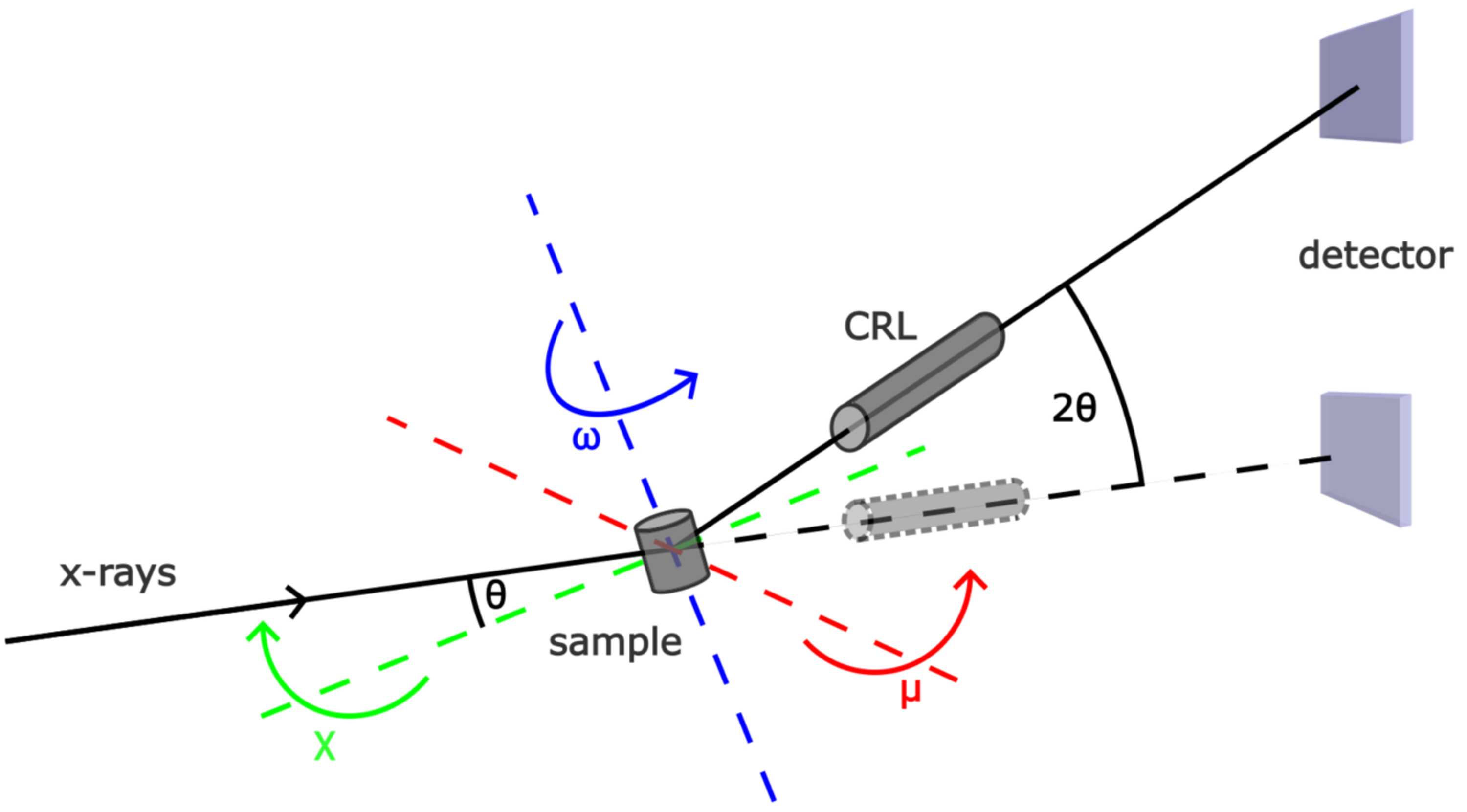
Figure 2
Schematic of the DFXM setup at the ID03 beamline at the ESRF. Depicted is the basic setup geometry with the dark-field (solid line) and bright-field (dashed line) configuration. In dark-field mode, the incoming beam is diffracted at the sample and the diffracting part of the sample is imaged by the CRL on the detector. Here, θ describes the Bragg angle. The CRL objective and the detector are positioned at an angle of 2θ with respect to the optical axis. μ, χ and ω are depicted as well. μ and χ can be used to investigate the mosaicity of a sample by bringing misoriented parts of the sample into diffraction condition. In bright-field mode, the CRL and the detector are in line with the incoming X-ray beam and the sample is imaged via absorption and phase contrast. |
 | JOURNAL OF SYNCHROTRON RADIATION |
ISSN: 1600-5775
 access