

 menu
menu


research papers
 | JOURNAL OF SYNCHROTRON RADIATION |
 access
Focusing, collimation, and beam expansion of high-energy X-rays with diamond refractive lenses

aAdvanced Photon Source, Argonne National Laboratory, 9700 S. Cass Ave., Lemont, IL 60439, USA, and bPALM Scientific, LLC, Naperville, IL, USA
*Correspondence e-mail: [email protected], [email protected]
Diamond is extremely well suited for synchrotron X-ray refractive optics. The effectiveness of diamond refractive lenses, fabricated by pulsed laser ablation, is demonstrated here for the focusing, collimation, and expansion of high-energy, undulator-source X-ray beams in the 40–70 keV photon energy range. The design of the lens elements and their mounting scheme allow the convenient feature of stacking both one-dimensionally and two-dimensionally focusing elements together in a self-aligning manner within the same holder for astigmatic manipulation, when needed. The CuCrZr alloy frames embedding the diamonds are suitable for thermal management, while possessing hardness. Collimating lenses, placed following a high-heat-load monochromator, are employed to increase the throughput of a subsequent narrow-angular-acceptance high-energy-resolution monochromator, after which the X-rays are focused to deliver a beam to coherent diffraction experiments on a long beamline. Also motivated and proposed is the concept of a convex beam-expander, which might seem counterintuitive given that it has higher attenuation on-axis. However, for high-energy X-rays from a low-emittance source on a long beamline, convex diamond beam-expanders could be practical. A proof-of-principle test result of this idea is presented.
Keywords: X-ray refractive lenses; X-ray optics; X-ray focusing; high-energy X-rays; beam expanders.
1. Introduction
Refractive and diffractive optics having the beneficial characteristic of in-line operation, i.e. a beam-transmission configuration, are often the choice for focusing X-rays. These include compound refractive lenses (CRLs) (Snigirev et al., 1996 ; Lengeler et al., 1999), saw-tooth refractive lenses (Cederström et al., 2002; Shastri et al., 2020), Fresnel-zone-based optics (Lider, 2017) and kinoforms (Aristov et al., 2000; Evans-Lutterodt et al., 2003; Shastri et al., 2014). CRLs, typically realized by stacked bi-concave lens elements, are particularly widespread in use due to some of their implementation simplicity aspects.
One should be reminded that, in distinction from visible light, X-ray refractive indices n in materials are very slightly less than one, resulting in reversed behavior wherein convex lenses are divergent and concave lenses are focusing. In comparing performance with regard to material selection specifically for CRLs, a figure-of-merit δ/μ is used, which takes credit for refractive strength and penalty for attenuation, thereby being closely proportional to the focused flux-density gain. Here, μ is the and δ = 1 − n. On this metric, lower atomic number Z materials always perform better, less so at high energies E, but more significantly at low energies where attenuation decreases sharply with Z, making Be commonly viewed as optimal. However, above 30 keV photon energy, the performance of Be over C becomes marginal, and the weak Be refraction δ results in inconveniently long CRL assemblies (a consideration not captured in a δ/μ assessment), since the number of bi-concave elements of curvature-radius R needed for a focal length f is

where δ ∝  . Here, the high density (and refraction) of diamond emerges as a benefit, making it an optimal material for CRLs up to 70 keV, where it starts to marginally outperform Si and Al, which catch up and are also commonly used, partly due to their having well developed fabrication/processing methods. In addition to its high density and low attenuation, diamond also offers the attractive features of chemical inertness, better thermal management under heat-load, and availability in single-crystal form that reduces scattering and preserves beam coherence.
After describing the fabrication and mounting of the diamond optics in Section 2, this article presents results from diamond CRLs applied to focusing (Section 3), collimation (Section 4), and beam-expansion (Section 5) with X-rays in the 40–70 keV energy range. Two high-energy X-ray undulator beamlines were used at the Advanced Photon Source (APS) at Argonne National Laboratory. One of them is the new High-Energy X-Ray Microscope (HEXM) long beamline 20-ID (Shastri, 2025), which was constructed as part of the recent APS upgrade (Kerby, 2023). The upgrade reduced the emittance (horizontal source size-divergence product) of the electron storage ring from 3100 pm rad to 42 pm rad, through the implementation of a multi-bend-achromat (MBA) storage ring design (Einfeld et al., 2014). The other beamline 1-ID (Shastri et al., 2020) has existed since well before the upgrade, and was used as a development site.
2. Lens fabrication and mounting
Although desirable in final form, diamond's properties of inertness and mechanical robustness pose fabrication challenges, particularly in chemical processing. However, high-intensity laser machining has been demonstrated to make diamond refractive optics (Polikarpov et al., 2015; Terentyev et al., 2015, Terentyev et al., 2017; Antipov et al., 2016; Wang et al., 2025), with femtosecond-pulsed ablation giving better quality and shaping flexibility over the cutting approach. The diamond optics demonstrated in this work were all made by ablation at PALM Scientific, LLC (URL: https://x-raylens.com/), for the most part using a method described by Antipov et al. (2016).
With the exception of the tested convex beam-expander (described later in Section 5.4), each small diamond lens element plate is embedded into its own precisely machined metal frame made from CuCrZr alloy. This metal was selected for its combined hardness and thermal conductivity qualities. The hardness is important for reproducible alignment in holders and the thermal conductivity would facilitate heat transfer from the diamond if used in high-power synchrotron white beams. Presented here, however, are only applications in low-power monochromatic beams.
The centered insertion of the single-crystal diamond (CVD-2A or HPHT grown) plates of 1 mm thickness and 1–2 mm diameter, into the frames, is done by press-fitting before the laser machining. The frame edges serve as placement fiducials in both the laser machining mount and the X-ray beamline mount. This ensures that the laser-machined lens elements' optical axes coincide when stacked in the beamline holder, which is a precision 90° V-block (Fig. 1). The proper concave profile for 2D focusing is paraboloid z = (x2 + y2)/2R, where z is along the optical axis, x, y are transverse coordinates, and R is the vertex radius used in equation (1). These shapes are plotted in Fig. 2(a) for various R-values used in this work. During laser machining, more material is removed near the center of the diamond to produce the paraboloid. For the 2D focusing elements, the frames are disks of  mm diameter and 2.00 mm thickness, shown in Figs. 1(a) and 1(e) (the furthest one of the three in the V-block). For a bi-concave element, the ablation is stopped after achieving the profile going to almost halfway depth, within 10–12.5 µm of the midplane. The piece is then turned over accurately to machine the opposite side similarly at the same location. This leaves 20–25 µm axis walls, through which the beam propagates in transmission, normal to the disk.
![[Figure 1]](tv5093fig1thm.gif) | Figure 1 Mounting of (a) a 2D focusing element circular frame and (b, c, d) various considered 1D focusing frames in a V-block, with (d) chosen. (e) Combining both 1D and 2D types in the same V-block, which is (f) rotated at 45° inclination for the cylinder axes of 1D focusing lenses to be oriented horizontally or vertically. |
![[Figure 2]](tv5093fig2thm.gif) | Figure 2 (a) Parabolic profiles for different values of R employed, truncated at apertures corresponding to nearly halfway depth into a 1 mm-thick plate. Optical microscope image in inset. (b) Transmission through diamond CRLs discussed here: long-focal-length test in Section 3 (solid line), collimation in Section 4 (dashed line), and focusing in Section 4 (dotted lines). On-axis transmission is slightly less than 1 due to the thin walls. Plotted are only one side of the axis due to symmetry. Vertical-line markers indicate 1/2 of the extent of the beam size illumination, as discussed in the main text. |
Due to the azimuthal symmetry of the 2D focusing paraboloid, the rotational freedom about the optical axis when placing the disks in the V-block is not important, unless one has reason for establishing an exact orientation. That case will be revisited below. However, with regard to implementing 1D focusing with planar-parabolic lens elements (z = y2/2R profile), their optical cylinder (plano) axes x must be parallel to one another, as the line focus quality is sensitive to such misalignments. So a frame design with at least one straight edge is needed. Square and octagonal [Fig. 1(b)] shapes were considered, but not adopted due to the geometrically over-constrained condition with instability arising if the 90° angles of the V-block and frame are slightly unequal. A uniquely constrained scheme is achieved with a circular shape extended with a tangential flat [Figs. 1(c), 1(d)]. The shape depicted in Fig 1(d) was adopted, and is shown in Fig. 1(e) in the two nearer elements, having their flats resting on different inclines of the `V', corresponding to a 90° change in the focusing plane. An added consideration was the higher precision expected for laser machining of planar-paraboloids if the cylinder axis is parallel to the frame's flat [Fig. 1(d)]. This would result in the focusing directions being diagonal at ± 45°. To obtain the desired vertical or horizontal focusing at 0° and 90°, the V-block was mounted at the beamline onto a 45°-inclined wedge [Fig. 1(f)], carried by a kinematic mount.
The frames have the feature of auxiliary holes, at equal distance from the center, which are used for stacking. Miniature rods are passed through two sets of holes in the stack and also through small compression springs at one end. Fasteners gripping the rods on both ends are adjusted to gently squeeze the springs and the lens stack together, while making sure all the frames' edges are properly seated in the V-block with the help of a comb-fingered leaf-spring pushing down from above [Fig. 1(f)]. Given that the circular sections of the 1D frames have the same 12.00 mm diameter as the round 2D frames, both 1D and 2D focusing elements can be combined into alignment on a single mount. This capability is used (Section 4) to focus X-rays on a long beamline, using an astigmatic lens combination to compensate for the beam already having been collimated in one plane only (for efficient high-resolution monochromatization).
One should note that it is also possible to package the 2D focusing lenses in the round-with-tangential-flat frames [Fig. 1(d)] used for the 1D lenses, if rotational position reproducibility is needed. This would arise if corrective optics are fabricated to compensate for the pre-characterized aberrations of a specific lens stack (Seiboth et al., 2017), since the matched corrector optic is valid only for the unique imperfection profile from the exact orientations of the constituent lens elements.
3. Long-focal-length focusing
The diamond refractive optics development and testing presented in this article were primarily motivated by long-focal-length applications (17 m < f < 106 m) in the new long beamline 20-ID-HEXM, to provide spot sizes of tens of microns. As a side note, for short focal lengths (0.7 m < f < 2.5 m), the plan was to employ saw-tooth refractive lenses, due to their ability to give submicron beams (Shastri & Moldovan, 2020), tunability and compactness, as opposed to the case of CRLs where the number of elements would become very large [N ∝ (E 2)/f from equation (1)]. Long-focal-length optics placements at HEXM are at distances s1 = 33 m and 75 m from the source, focusing to sample positions at distances s1 + s2 = 69 m and 181 m, corresponding to values of focal length f = (1/s1 + 1/s2)−1 = 17.2 m, 27 m, and 44 m. There is also a scheme (Section 4) to collimate (s2 = ∞) the beam at s1 = f = 31 m, followed by optics at 75 m, focusing to 181 m, corresponding to s1 = ∞, f = s2 = 181 m − 75 m = 106 m. The main point here is that the smallest, i.e. most demanding, f-value among the various configurations just listed is 17.2 m, which happened to be close to f = 17.37 m in a set-up available at another high-energy beamline 1-ID. This made 1-ID a suitable testing site for the diamond CRL development in advance of the APS upgrade and construction of HEXM. Even though there was a significant source emittance reduction in the upgrade, pre-upgrade focusing optics tests are meaningful, since the vertical source size decreased marginally (in the current initial phase), whereas it was the large horizontal size that decreased dramatically to become comparable to the vertical.
The focusing results in this section are from 50 keV X-rays at beamline 1-ID (pre-upgrade, third harmonic of a 1.8-cm-period, 1.1 m-long superconducting undulator), with the CRL at s1 = 38 m, and focus at s1 + s2 = 70 m from the source, corresponding to f = 17.37 m. Combining this with R = 100 µm bi-concave elements and δ = 2.9 × 10⁻⁷ refraction in diamond, results in N = 9.9 from equation (1), or close to 10 elements. The radius R = 100 µm was chosen, because for such paraboloids machined almost halfway into a 1 mm plate, the spatial aperture diameter is 2[2(100 µm)(0.5 mm)]1/2 = 0.63 mm, which is adequately matched to the undulator beam size in the upgraded APS. For the tests at 1-ID, the CRLs were illuminated by a 0.44 mm × 0.44 mm beam, indicated by the vertical marker at 0.22 mm on the solid-line transmission curve in Fig. 2(b). Focal spot profiles are shown in Fig. 3, measured by a small imaging detector consisting of a scintillator, followed by a 90° reflection mirror, 5× optical objective and a planar sensor array with 5.86 µm pixels, corresponding to 1.17 µm at the X-ray imaging plane.
![[Figure 3]](tv5093fig3thm.gif) | Figure 3 Focused beam line-profiles and images from (a) 2D focusing and (b) 1D focusing tests in a 38 m:32 m demagnification ratio (f = 17.37 m). |
Horizontal and vertical focal spot profiles from 2D focusing are shown in Fig. 3(a) for three sets of CRLs. The wider horizontal profiles are compressed by a factor of six to be displayed on the same scale. After measuring one set of ten elements (solid lines), they were replaced by another equivalent set of ten (dashed lines). In the third measurement, five of the ten 2D focusing elements of the second set were removed and replaced with five 1D-vertically focusing elements and five 1D-horizontally focusing elements, all having R = 100 µm, making an equivalently focusing 1D/2D-mixed set of 15 elements [Fig. 1(f)]. The result from this mixed set is also shown in Fig. 3(a) (vertical profile/`+' symbols, horizontal profile/dotted line). The focusing from ten 1D-vertically focusing lenses, i.e. without horizontal focusing, is shown in Fig. 3(b). These were made to have a spatial acceptance of 0.75 mm in the plano direction.
The essentially indistinguishable focal profiles point to the reproducibility of the lens elements fabrication and reliability of the mounting scheme, achieving proper relative alignment for 1D, 2D or their combination of focusing elements. The vertical foci full-width at half-maxima (FWHM) of 30 µm obtained for 1D and 2D focusing were also confirmed with a Si saw-tooth refractive lens (not shown here) at the same location. This is 36% larger than the expected value of 22 µm based on the geometrical demagnification of the assumed 26 µm vertical source size. In addition to slight blooming in the imaging detector, this discrepancy could be from an increase in the effective source size by the vertically diffracting bent double-Laue monochromator (Shastri et al., 2002), whose crystal bend-radii were not optimally adjusted for vertical source size preservation at this energy (Lienert et al., 2001; Shastri et al., 2007). The horizontally focused size of 430 µm is smaller than the expected value of 535 µm from demagnification of the 635 µm horizontal source. This is possibly due to the 0.5 mm × 0.5 mm white beam aperture setting upstream in the beamline which, combined with the 0.44 mm × 0.44 mm aperture just before the CRLs, resulted in not all points on the lens system viewing the full horizontal source, making it effectively smaller. The flux-density-gain measured in the 2D case was 27 (expected value of 36), and in the 1D case was 16 (expected value of 23), with the latter case being lower due to the absence of horizontal focusing.
Some additional results can be reported that are not explicitly presented here. The 2D focusing was also conducted with N = 10, R = 100 µm elements that had undergone a polishing process reducing the surface roughness from Sa < 300 nm to < 30 nm (Celestre et al., 2022). However, no noticeable difference in performance was discerned at this energy of 50 keV, within the sensitivity of the imaging detector used. Neither were any differences noted between CVD-2A and HPHT-2A grown diamonds. Half- and quarter-strength refractive elements of biconcave R = 200 µm and R = 400 µm were also tested. In a 2D focusing case with ten elements, this was done by removing one element, confirming a clear degradation of the focus, and then restoring it completely by replacing the missing element with a half-strength plus two quarter-strength refractors. This properly functioning behavior of weaker refractive elements was confirmed with the 1D focusing CRL system as well. Generally, having weaker lens elements of larger radii is important to focus optimally in a fixed energy and distance configuration. In the tests here, the correct number of elements happened to be very close to a whole number (9.9), which is not always the case, as occurs in the next section. Finally, to verify smaller-radius laser-machining capability, a 2D focusing CRL was tested with elements of half the radius, i.e. R = 50 µm bi-concave, and consequently N = 5, which gave a 30 µm vertical focus nearly indistinguishable from the rest.
4. Collimation for high-resolution monochromatization and focusing
This section illustrates the application of diamond CRLs within an X-ray optical system at the long beamline HEXM (APS post-upgrade, in timing-mode), for Bragg coherent diffraction imaging (BCDI) experiments, which is one of the methods available there. The aim there is to isolate and examine the X-ray diffraction patterns from coherently illuminated individual crystalline grains up to ∼10 µm size, to determine their shape and sub-grain strain fields (Ulvestad et al., 2014; Maddali et al., 2020).
The detailed analysis, justifying the technical requirements based on the scientific case, leading to a full description of the optics and how the beam coherence properties are controlled, will be presented elsewhere. Here, the conditions to be met are stated. A focused beam of a few tens of microns is needed. In addition to transversely coherent illumination, sufficient longitudinal coherence is also required, corresponding to a narrow monochromaticity of ΔE/E ≃ 5 × 10⁻⁶. High X-ray energies are desirable for penetration into samples and environments, but coherent flux decreases and high-resolution monochromatization becomes more challenging as the energy is increased. Weighing opposing constraints to meet the requirements feasibly, E = 42 keV was selected for most BCDI experiments.
The full X-ray optical scheme is depicted in Fig. 4. Radiation from the fifth harmonic of a 2.1 cm-period, 4.7 m-long permanent-magnet undulator source was monochromated to E = 42 keV, ΔE/E = 6.4 × 10⁻⁴ with a horizontally diffracting, cryogenically cooled, bent double-Laue Si(111) high-energy monochromator (HEM) (Shastri et al., 2002). Further monochromatization (Shastri, 2004) to the desired ΔE/E = 4.8 × 10⁻⁶ was achieved with a four-reflection, vertically diffracting, Si(440) high-resolution monochromator (HRM), which has a small vertical angular acceptance of 740 nrad.
![[Figure 4]](tv5093fig4thm.gif) | Figure 4 Optics scheme for BCDI at HEXM. Slits, monochromators (HEM, HRM), and CRLs (CL, FL) are shown. Source size, expected focus size (FWHM), distances, focal lengths f, and magnification ratios are given. The middle (and lower) panels separately represent component actions in the vertical (V) [and horizontal (H)] planes. |
To enhance the efficiency of the HRM, a 1D vertically collimating diamond CRL (denoted CL in Fig. 4) was placed in between the HEM and HRM, with focal length f = 31 m equal to its distance from the source (Baron et al., 1999). For bi-concave R = 100 µm elements, equation (1) gives N = 3.9. So four lens elements of the 1D type were mounted in this position for vertical beam collimation.
Focusing to the 181 m sample location was done by a diamond CRL at 75 m from the source (FL in Fig. 4). This optic had different f-values horizontally and vertically. Horizontally one must have f = (1/s1 + 1/s2)−1 = 44 m from s1 = 75 m and s2 = 181 m − 75 m = 106 m, which would be achieved with Nhoriz = 2.75 1Dhoriz elements of R = 100 µm [equation (1)]. Vertically, since the beam is already collimated by CL, one would need f = 181 m − 75 m = 106 m, which corresponds to Nvert = 1.15 1Dvert elements of R = 100 µm. Representing this astigmatic condition symbolically and manipulating it to simplify the arrangement, FL would be composed of
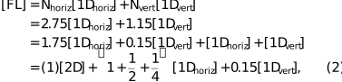
where the identity [1Dhoriz] + [1Dvert] = [2D] has been used. Focusing by FL was implemented according to the last expression of equation (2), but omitting the 0.15-strength 1Dvert refractive correction, since CL was already slightly over-refracting (using N = 4, instead of 3.9 of the same type). So four elements were used for FL: a 2D element, a 1Dvert element, a half-strength 1Dvert (R = 200 µm), and a quarter-strength 1Dvert (R = 400 µm) refractor. This mixed astigmatic set was mounted in a single V-block, as described in Section 2.
The white beam slits at 27 m (Fig. 4) were set to 0.22 mm × 0.30 mm. The horizontal size was adjusted to 0.22 m for the beam to expand linearly to 0.62 mm at 75 m. This just matches the parabolic spatial aperture of the 2D refractive element in the FL optic [see the R = 100 µm curve in Fig. 2(a) and the marker on the lower dotted-line curve in Fig. 2(b), which plots the transmission of FL going horizontally off-axis]. On the other hand, the vertical slit size can be larger, as the beam is not expected to linearly expand vertically all the way, because of the collimating CL optic at 31 m, after which the vertical beam size should be constant. So 0.30 mm was selected for the white beam vertical aperture, being sufficient to pass through a large fraction of the monochromatic undulator radiation central cone. This is reflected in the same abscissa marker positions in the Fig. 2(b) dashed-line and upper dotted-line curves, which plot the transmission of CL and FL, respectively, going vertically off-axis.
The final focused beam at 181 m was expected to be 41 µm × 80 µm, based on the magnification ratios 106 m: 75 m and 106 m: 31 m applied to the 29 µm × 24 µm source size. When focal spot sizes larger than the source are required, as is the case here, a long beamline allows achieving this goal through magnification optics configurations. This is important as further reduction in the vertical source size, i.e. the storage ring coupling, is planned (APS brightness-mode).
Using detectors similar to the one used in Section 3, beam images were taken at the 181 m location [Figs. 5(a), 5(c), 5(d), 5(e), 5(f)] and at the 69 m location [Fig. 5(b), 6 m before the FL optic], for various configurations of the CL, HRM, and FL in or out of the beam. With CL, HRM, and FL removed, Fig. 5(a) confirms the linear beam expansion in both dimensions from the 0.22 mm × 0.30 mm white beam slits at 27 m.
![[Figure 5]](tv5093fig5thm.gif) | Figure 5 Beam images recorded at 181 m and 69 m [(b) only] in the Fig. 4 set-up, for various component combinations (of CL, HRM, and FL) inserted into or retracted from the beam. All have been scaled to the same field-of-view for spatial size comparison. The (f) focused beam whose profiles and zoomed-in image are in Fig. 7. |
Introducing the vertically collimating CL stops the vertical expansion in the propagation, but leaves the horizontal expansion unaffected [Figs. 5(b), 5(c)]. The striated structure in Fig. 5(c) is caused by an attenuator put into the beam at 67 m (i.e. 114 m upstream), since the collimated radiation intensity was saturating the detectors at both 69 m and 181 m. Fig. 5(b), which also required attenuation, does not show this artifact as it was taken 2 m after the attenuator, not allowing enough distance for the pattern to emerge through beam propagation. The measured transmission through CL was 0.965, in agreement with the expected value of 0.960 from an integral-average of the Fig. 2(b) dashed-line curve over the beam.
Introducing the HRM in addition to CL gave image Fig. 5(d), which is similar to Fig. 5(c), but weaker in flux by a factor of 1/113, consistent with the slightly more than two orders of magnitude reduction in bandwidth ΔE. This observed flux drop being closely proportional to the HRM-to-HEM bandwidth ratio, without any additional penalty from the small HRM angular acceptance, is indicative of effective vertical collimation by CL. It takes the incident vertical divergence of 0.3 mm / 27 m = 11 µrad and delivers it for efficient passage, without significant loss, through the HRM angular acceptance of 740 nrad.
The collimation performance can be ascertained in two other ways. One can conduct a vertical angular rotation scan of the entire HRM, sweeping its angular acceptance window through the incident beam, and monitor its throughput (Fig. 6) to infer the divergence of the collimated X-rays. The measured width of 1.2 µrad is close to the expected value of 1.1 µrad, based on a convolution of the HRM's 740 nrad acceptance and the residual divergence of 770 nrad that remains uncollimated from the source size divided by distance 24 µm/31 m. The dramatic enhancement of the HRM efficiency by CL was also confirmed by removing CL with the HRM in place. Doing this reduced the flux after the HRM by a significant factor of 1/8.5, with the [Fig. 5(e)] thin-beam image showing the HRM behaving as a narrow angular slit. This thin beam's 147 µm vertical size is in approximate agreement with the HRM angular acceptance 740 nrad (181 m) = 134 µm, broadened by the 24 µm vertical source size.
![[Figure 6]](tv5093fig6thm.gif) | Figure 6 Flux transmitted through the HRM as a function of its overall vertical rotation angle, with the collimating diamond CRL in place before it. |
Adding the final optical element FL of the set-up focused the beam to 49 µm × 66 µm [Figs. 5(f) and 7, taken with attenuation]. The measured transmission of FL was 0.90, in reasonable agreement with the expected 0.92, based on the product-integral-average of the two dotted-line transmissions in Fig. 2(b). The horizontal focus is larger than the expected 41 µm, whereas the vertical focus is smaller that the expected 80 µm, both discrepancies being about 20%. The larger horizontal spot size can arise from two causes. One is the horizontally diffracting bent double-Laue monochromator slightly enlarging the effective source size. The second is from the 4.7 m-long undulator actually being composed of two 2.35 m devices, without an electron trajectory corrector magnet in between them, also possibly resulting in a larger horizontal source. The smaller than expected vertical focus can be explained only by the electron beam having a smaller vertical size than stated, either from a lower storage ring vertical emittance or beta function.
![[Figure 7]](tv5093fig7thm.gif) | Figure 7 Horizontal and vertical line-profiles through the final focal spot image obtained in the Fig. 4 X-ray optical set-up. |
5. Beam expansion
This section covers the motivation for having beam-expansion optics at the long beamline HEXM, the viability of convex (versus concave) CRL optics for this purpose and a test of this concept conducted at beamline 1-ID (pre-upgrade). The MBA storage ring design was driven by a considerable subset of synchrotron experiments benefiting from low-emittance beams, whose small angular divergences result in small beam sizes even at long distances. However, some experiments are better satisfied by larger beams. For the upgraded APS operating in the MBA standard-mode, the monochromatic beam size of high-energy undulator radiation is 2.1 mm × 2.4 mm (FWHM) at the 181 m experiment location, whereas up to 4 mm beams are sometimes optimal for techniques such as tomography and polycrystalline grain-mapping (Suter et al., 2006) on large specimens. Working directly with a larger field-of-view is more desirable than stitching together smaller ones in data processing. Expanding the beam, even in one direction (i.e. horizontally), typically addresses the need, e.g. in tomography, where having a sufficient field-of-view perpendicular to the rotation axis eliminates stitching. For grain-mapping, in fact, expansion in only one direction is appropriate, since the technique is specifically based on having 1D focused line-illumination, in this context wanting a ∼4 mm × 0.001 mm beam. Unnecessarily expanding the beam in the focusing direction would be a detrimental mismatch to the small spatial aperture of the 1D focusing optic (i.e. saw-tooth refractive lens) operating at short focal length close to the sample.
5.1. Approaches
A controlled introduction of magnetic field error in the undulator source by tapering the device's gap would degrade the central radiation cone and expand the beam, but would do so in both directions, and would not be ideal for generating line-focused beams. Also, superconducting undulators, planned for installation at HEXM in the near future, typically do not have a feature equivalent to tapering, as they are designed with a fixed gap. So beam expansion by the simple insertion of a refractive optic that operates in-line would be attractive. The transparence of diamond at high X-ray energies, combined with its refractive strength, makes it potentially efficient on a long beamline where low refraction can create an adequate expansion effect over distance.
Other optical approaches to expansion involve crystals (asymmetric Bragg or bent Laue geometries, Christensen et al., 1992; Korytár et al., 2003; Martinson et al., 2015) and curved mirrors (or multilayers). Asymmetric crystals are impractical at high energies due to beam incidence at angles smaller than the already grazing Bragg angles. Bent/curved optics involve nontrivial adjustment procedures. Most of these schemes are not in-line, even though they might be fixed-offset, and are not amenable to offering on-demand expansion/no-expansion with the beam position fixed. Fresnel zone plates are in-line, but difficult to fabricate at high energies (Shastri et al., 2001), and are accompanied by other diffraction orders and structure in the beam off-focus. This leads to the consideration of a refractive optic. A refractive expander based on a multi-lens generated beam overlap/interference has been demonstrated with Si (Zverev et al., 2021), but has a small spatial acceptance (<100 µm) in the direction perpendicular to expansion due to etching process depth limitations.
5.2. Refractive expansion
A refractive optic that directly expands X-rays would be convex, as shown in Fig. 8(a). Assume a beam of intrinsic, non-expanded size A at the experiment distance L from the source that has to be expanded by a factor of B (to the desired size BA), by placement of a convex lens at position s1. This effectively moves the source closer to a virtual position at distance |s2| upstream of the optic. One treats s2 as negative, in accordance with the sign conventions for the lens equation f = (1/s1 + 1/s2)−1 that will be used. One should emphasize that B is the ratio of the expanded beam to the non-expanded beam at the same distant location L. For fixed aperture h at s1, with no expander, the beam at L will have size A = hL/s1. With the convex (direct) expander, the size at L becomes BA = h(L − s1 + |s2|)/|s2|, giving the expansion factor

Solving for the placement of the secondary (virtual) source gives

![[Figure 8]](tv5093fig8thm.gif) | Figure 8 Illustrations of the operation of (a) a convex (divergent) lens that directly expands the beam and (b) a concave (convergent) lens that focuses the beam, which then expands in further propagation. The smaller transverse extent needed for small beams (inner lens outline in blue, compared to the outer-green) reduces the on-axis thickness and attenuation of the convex optic. |
Conducting a similar analysis for the case of the concave (focusing) expander in Fig. 8(b), the expanded beam size at L is B′A = h(L − s1 − s2)/s2, giving an expansion factor

with the secondary (real) source occurring at

Knowing s1 and having determined s2 from equations (4) and (6), one can determine the optic's focal length f = (1/s1 + 1/s2)−1, where f < 0 and f > 1 result for convex and concave cases, respectively, depending on whether equation (4) or equation (6) is used. The expressions for B and B ′ do not take into account the attenuation profile of the expander. For the convex expander which has more attenuation on axis, there would be a beam profile flattening effect that would make the apparent expansion larger than that given by equation (3). For the concave expander which has more attenuation off-axis, there would be a narrowing effect that would make the expansion less than that given by equation (5).
5.3. Horizontal expander proposed for HEXM
Considering the application of a direct diamond expander towards HEXM, one would want B ≃ 2 to double the horizontal beam size from 2.1 mm to 4 mm at L = 181 m. The available position for placement of this optic is at s1 = 33 m, which gives a virtual s2 = −14.8 m using equation (4) and f = (1/33 m − 1/14.8 m)−1 = −27 m from the lens equation (the negative value of f being consistent with a divergent lens). Assuming a 1D expanding CRL of R = 100 µm bi-convex elements, equation (1) still applies, giving N = 11–12 for 65–70 keV X-rays typical for tomography and grain-mapping. Selecting N = 11 and using equation (3), one can plot the expansion factor B as a function of energy [Fig. 9(a)], showing the potential applicability of the same 11-element bi-convex CRL optic over a wide range, with roughly the same expansion factor. Fabrication aspects aside, the R = 100 µm choice is arbitrary, and so the same behavior would result if one were to employ instead a CRL with reduced N = 6 and compensated with more refractive R = 100 µm (6/11) = 54.5 µm.
![[Figure 9]](tv5093fig9thm.gif) | Figure 9 Plot of the expansion factor B versus energy for the (a) proposed convex CRL expander for the HEXM beamline and (b) the one tested at beamline 1-ID. The design parameters of the expanders are also given, with microscope images of the tested optic. |
At 33 m from the source, which is the intended location of the horizontal beam expander, the 70 keV incident beam profile is calculated to be a Gaussian of 0.39 mm FWHM, plotted as a dashed line in Fig. 10(a). This is for the seventh harmonic of the same undulator as in Section 4, with the storage ring operating in standard mode. Based on this size, a 500 µm horizontal extent for this 11-element parabolic CRL, as drawn in Fig. 9(a), is sufficient. It is important not to make the convex lens extent larger than necessary, as that increases the on-axis thickness and overall attenuation, which can be understood by comparing the blue and green outlines for the convex optic in Fig. 8(a). The transmission fraction through the CRL is given by the dashed-dotted line in Fig. 10(a), being minimum in the center and terminating at the value 1 where the lens tapers down to zero thickness at the edges ± 0.25 mm. Multiplying the beam profile with the transmission gives the transmitted beam intensity profile (solid line), which also terminates at the lens edges. However, to avoid any spurious edge effects, one should not illuminate the CRL horizontally all the way to these edges, but avoid 0.05 mm at both ends, thereby restricting oneself to a 0.4 mm aperture. This aperture, which would be implemented by slits right before the CRL, is represented by the vertical dotted lines at ± 0.20 mm [Fig. 10(a)].
![[Figure 10]](tv5093fig10thm.gif) | Figure 10 For the proposed expander at the long beamline HEXM, plots of (a) the calculated undulator beam horizontal profile, convex expander transmission fraction and transmitted profile at 33 m and (b) the non-expanded, convex-expanded and concave-expanded profiles at 181 m. |
At 181 m, the calculated non-expanded horizontal beam profile [Fig. 10(b), dashed line] is essentially identical to the 33 m profile, but stretched horizontally by the distance propagation ratio 181 m/33 m, giving a Gaussian FWHM of 2.1 mm. The beam profile at 181 m with the expander in place at 33 m [Fig. 10(b), solid line] is obtained by taking the transmitted profile in Fig. 10(a) and stretching it by the propagation distance ratio 181 m/33 m, and additionally by the expansion factor B = 1.88 expected for this expander optic/configuration with 70 keV X-rays from the curve in Fig. 9(a). The result is the desired expanded horizontal beam of 4 mm size [Fig. 10(b), solid line]. The sharp cut-offs at ± 2.05 arise from the 0.4 mm slit aperture at the expander projected to 181 m with beam propagation amplified by the expander B-value, i.e. 0.4 mm (181 m / 33 m) 1.88 = 4.1 mm. The plotted profiles at 181 m are properly scaled for intensity distribution comparisons relative to one another, with the CRL attenuation included when present. Evaluating integrals of the convex expander and non-expanded intensity profiles over ± 2 mm and taking the ratio gives a efficiency of 58% for the optic.
For comparison, one can examine the performance of a concave diamond expander [Fig. 8(b)] for the same conditions s1 = 33 m, L = 181, and seeking B′ = 2 at 70 keV. Using equation (6) gives s2 = 12.4 m, followed by f = (1/33 m + 1/12.4 m)−1 = 9 m, implying that this expander focuses the beam horizontally at 12.4 m downstream, before it begins to grow. From equation (1), this could be perhaps implemented with N = 18–19 bi-concave 1D focusing elements of R = 50 µm. The beam expanded by this optic would have a profile at 181 m given by the dotted line in Fig. 10(b). Given that this exercise is aimed at delivering a beam for a 4 mm specimen, one can take the ratio of integrated flux under this profile to that of the non-expanded beam over ± 2 mm, as done above for the convex expander. This gives a concave optic efficiency of 60%. The efficiencies of the two optics are comparable, but the convex expander provides a flatter profile over the desired 4 mm beam. In fact, the concave expander beam is less than 4 mm FWHM at 181 m with intensity at ± 2 mm significantly less than at the center. This is because, even though one sought an expansion factor of B′ = 2, the equations (5) and (6), used do not include the optic's attenuation profile, which has a narrowing effect as pointed out earlier. This effect in the concave expander is not straightforward to correct, since reducing the profile-narrowing by making the attenuation more uniform decreases the refractive strength, implying larger f and s2, which counterproductively reduces B′ in equation (5). Making the convex expander parabolic might not be essential. However, altering its curvature away from the axis also involves a trade-off between expansion effect and attenuation.
5.4. Expander test at 1-ID
A demonstration of the convex expander idea was conducted at beamline 1-ID (pre-upgrade), primarily to ascertain the fabrication feasibility of such an optic by laser machining and whether it actually behaves as expected. This was done in the same distance/placement set-up as for the long-focal-length focusing in Section 3, i.e. s1 = 38 m and L = 70 m, with the attempt here to achieve an expansion B ≃ 2. Equation (4) gives a virtual s2 = −11.9 m and f = (1/38 m − 1/11.9 m)−1 = −17 m. A CRL device candidate for 50 keV X-rays, from equation (1), would be characterized by 1D bi-convex N = 5 elements having R = 50 µm, as drawn in Fig. 9(b), which plots its expansion factor B over 40–60 keV. The same figure also shows microscope images of the laser-machined convex CRL with these parameters. Unlike the other CRLs in this article, where each element is separate and in its own frame, for this optic all five elements were part of the same monolithic single crystal. The lens elements' parabolic shapes on one side of the optical axis were machined with the laser incident normal to a 0.5 mm-thick plate, near its edge, after which the plate was turned over to machine the other side of the optical axis, in the end exposing bi-convex pillars protruding away from the edge. Perpendicular to the optical axis, the CRL had a spatial extent of 0.31 mm (beam-expansion direction) and 0.78 mm pillar length (plano direction).
The test was done oriented for vertical beam expansion due to the small vertical source size, compared to the significantly larger horizontal source size, of the pre-upgrade APS. This resulted in the sharpness of vertically beam-defining slit edges at the expander being preserved well in propagation, giving clear beam sizes at 70 m for analysis. To avoid lens edge artifacts, the full 0.31 mm extent of the expander was not illuminated. Excluding 0.05 mm at both edges, the vertical aperture just before the expander defined a 0.21 mm beam. The horizontal beam illumination was 0.6 mm, which was less than the pillar length. Test results of this expander at 41, 50 and 60 keV are shown in Fig. 11 and Table 1. As expected, the non-expanded beam size at 70 m did not change with energy and agreed exactly with the linear increase with distance 0.21 mm (70 m / 38 m) = 0.39 mm. The expanded beam did change in size, showing B decreasing with energy as the refraction weakens, in good agreement with the calculation in Fig. 9(b).
| ||||||||||||||||||||||||||||||
![[Figure 11]](tv5093fig11thm.gif) | Figure 11 Images and vertical beam profiles, with and without the convex vertical beam expander, obtained at various energies at beamline 1-ID. Beam sizes are given in Table 1 . |
The beams show (Fig. 11) a non-uniform intensity structure in the expansion direction. SEM characterization was not carried out on the present convex prototype; however, the artifact is consistent with residual spatially correlated surface profile discontinuities from laser machining. Similarly fabricated (but 1D concave) single-crystal diamond refractive lenses have shown SEM-visible surface morphology of laser-induced, periodic, grooved-profile features that affect the transmitted/focused X-ray beam (Terentyev et al., 2017). Such effects could be mitigated by modifying the laser machining process and parameters, and by employing polishing methods, as have been developed for concave lenses (Celestre et al., 2022). One should also note that instead of the monolithic multi-pillar device shown here, a stacked set of convex elements in separate frames could offer advantages in performance and flexibility, as presently done for the concave CRLs.
Although expansion in one direction would often be sufficient (as image reconstruction methods from data are typically layer-independent), some comments on bi-directional expansion can be made. Extending the approach used here to laser machine a monolithic, 2D convex CRL device might not be feasible. Also, an orthogonally oriented pair of 1D expanders would suffer from the combined on-axis attenuation of both sets. Instead, one might laser machine individual convex refractive elements in separate frames, as mentioned above.
6. Summary and outlook
This article highlights the versatility of diamond refractive optics at high X-ray energies, particularly in the 40–70 keV range, where diamond's density makes it more practical than Be from the viewpoint of device lengths, and where it outperforms Al and Si in transmission. Furthermore, in single-crystal form, scattering and decoherence effects are reduced. Demonstrated here are applications to focusing, collimation, and beam expansion. Laser-machined diamond CRL elements in CuCrZr frames were described, with a frame design that allows for combining 1D and 2D focusing elements in the same V-block mount in a self-aligning manner, easily enabling astigmatic configurations. 2D element frames are circular, whereas 1D focusing element frames have a flat, permitting precise orientation for either horizontal or vertical focusing (or collimation). The importance of having lower strength refractor elements available to fine-tune the focal length was also shown. Although mounting was done manually here, automated insertion/removal of elements from the V-block by actuators could be implemented (transfocator concept, Vaughan et al., 2011; Duller et al., 2016; Shu et al., 2018). The choice of CuCrZr for the frames gives them hardness and high thermal conductivity for high thermal load conditions.
Long-focal-length focusing tests with diamond CRLs at 50 keV showed reasonably close to expected performance (tens of microns), acceptable for long-focal-length applications. Short-focal-length tests were not done because of the large number of elements required at high energies and the availability of saw-tooth refractive lenses for that purpose. However, pursuing short focal lengths (∼1 m) with diamond CRLs at high energies is still motivated by interest in high-resolution transmission X-ray microscopes (Marschall et al., 2014; Shastri et al., 2015) for tomography and dark field microscopy (Pedersen et al., 2020). If needed, corrector lenses could be used to achieve optimal performance in this limit, as demonstrated by Wang et al. (2025) to achieve nanofocusing by diamond CRLs at lower energies.
The diamond optics play a critical role in the X-ray optical system for conducting BCDI experiments at the long beamline HEXM, illustrating in a unified way the ingredients of focusing, collimation, integration of 1D and 2D focusing elements in the same mount, and optimization using lower strength refractors. Particularly noteworthy is the nearly ideal performance of the collimation optic which reduces the > 10 µrad beam divergence to match the sub-microradian angular acceptance of a 200 meV high-resolution crystal monochromator at 42 keV.
Finally the concept of a convex beam expander, made from diamond, was explored and shown to have merit for the case of high-energy X-rays at a long beamline with a low-emittance source. A prototype was tested, showing the desired behavior over a wide energy range. This type of expander could find applicability given the advent of numerous low-emittance synchrotron sources dedicated toward high-energy radiation (e.g. APS-U, SPring-8-II, HEPS and PETRA-IV).
Funding information
Research conducted at the APS at Argonne was supported by the US Department of Energy, Office of Science, under Contract No. DE-AC02-06CH11357. Section 4 data were obtained under beam time award DOI 10.46936/APS-188858/60013679.
References
 Antipov, S., Baryshev, S. V., Butler, J. E., Antipova, O., Liu, Z. & Stoupin, S. (2016). J. Synchrotron Rad. 23, 163–168. Web of Science CrossRef CAS IUCr Journals Google Scholar
Aristov, V., Grigoriev, M., Kuznetsov, S., Shabelnikov, L., Yunkin, V., Weitkamp, T., Rau, C., Snigireva, I., Snigirev, A., Hoffmann, H. & Voges, E. (2000). Appl. Phys. Lett. 77, 4058–4060. CrossRef CAS Google Scholar
Baron, A. Q. R., Kohmura, Y., Ohishi, Y. & Ishikawa, T. (1999). Appl. Phys. Lett. 74, 1492–1494. Web of Science CrossRef CAS Google Scholar
Cederström, B., Lundqvist, M. & Ribbing, C. (2002). Appl. Phys. Lett. 81, 1399–1401. Web of Science CrossRef CAS Google Scholar
Celestre, R., Antipov, S., Gomez, E., Zinn, T., Barrett, R. & Roth, T. (2022). J. Synchrotron Rad. 29, 629–643. Web of Science CrossRef CAS IUCr Journals Google Scholar
Christensen, F. E., Hornstrup, A., Frederiksen, P., Nilsson, C., Grundsøe, P., Ørup, P., Jacobsen, E., Schnopper, H. W., Lewis, R. & Hall, C. (1992). Rev. Sci. Instrum. 63, 1168–1171. CrossRef CAS Web of Science Google Scholar
Duller, G. M. A., Stallwood, A. & Hall, D. R. (2016). Proceedings of the 9th International Workshop on Mechanical Engineering Design of Synchrotron Radiation Equipment and Instrumentation (MEDSI2016), 11–16 September 2016, Barcelona, Spain, pp. 345–347. Google Scholar
Einfeld, D., Plesko, M. & Schaper, J. (2014). J. Synchrotron Rad. 21, 856–861. Web of Science CrossRef CAS IUCr Journals Google Scholar
Evans-Lutterodt, K., Ablett, J. M., Stein, A., Kao, C.-C., Tennant, D. M., Klemens, F., Taylor, A., Jacobsen, C., Gammel, P. L., Huggins, H., Bogart, G., Ustin, S. & Ocola, L. (2003). Opt. Express 11, 919–926. PubMed Google Scholar
Kerby, J. (2023). Synchrotron Radiat. News 36(4), 26–27. CrossRef Google Scholar
Korytár, D., Mikulík, P., Ferrari, C., Hrdý, J., Baumbach, T., Freund, A. & Kubena, A. (2003). J. Phys. D Appl. Phys. 36, A65–A68. Google Scholar
Lengeler, B., Schroer, C., Tümmler, J., Benner, B., Richwin, M., Snigirev, A., Snigireva, I. & Drakopoulos, M. (1999). J. Synchrotron Rad. 6, 1153–1167. Web of Science CrossRef IUCr Journals Google Scholar
Lider, V. V. (2017). J. Surf. Investig. 11, 1113–1127. CrossRef CAS Google Scholar
Lienert, U., Keitel, S., Caliebe, W., Schulze-Briese, C. & Poulsen, H. F. (2001). Nucl. Instrum. Methods Phys. Res. A 467–468, 659–662. CrossRef CAS Google Scholar
Maddali, S., Park, J.-S., Sharma, H., Shastri, S., Kenesei, P., Almer, J., Harder, R., Highland, M. J., Nashed, Y. & Hruszkewycz, S. (2020). Phys. Rev. Appl. 14, 024085. CrossRef Google Scholar
Marschall, F., Last, A., Simon, M., Kluge, M., Nazmov, V., Vogt, H., Ogurreck, M., Greving, I. & Mohr, J. (2014). J. Phys. Conf. Ser. 499, 012007. CrossRef Google Scholar
Martinson, M., Samadi, N., Bassey, B., Gomez, A. & Chapman, D. (2015). J. Synchrotron Rad. 22, 801–806. Web of Science CrossRef IUCr Journals Google Scholar
Pedersen, A. F., Chamard, V., Detlefs, C., Zhou, T., Carbone, D. & Poulsen, H. F. (2020). Phys. Rev. Res. 2, 033031. Web of Science CrossRef Google Scholar
Polikarpov, M., Snigireva, I., Morse, J., Yunkin, V., Kuznetsov, S. & Snigirev, A. (2015). J. Synchrotron Rad. 22, 23–28. Web of Science CrossRef CAS IUCr Journals Google Scholar
Seiboth, S., Schropp, A., Scholz, M., Wittwer, F., Rödel, C., Wünsche, M., Ullsperger, T., Nolte, S., Rahomäki, J., Parfeniukas, K., Giakoumidis, S., Vogt, U., Wagner, U., Rau, C., Boesenberg, U., Garrevoet, J., Falkenberg, J., Galtier, E. C., Ja Lee, H., Nagler, R. & Schroer, C. G. (2017). Nat. Commun. 8, 14623. Web of Science CrossRef PubMed Google Scholar
Shastri, S. D. (2004). J. Synchrotron Rad. 11, 150–156. Web of Science CrossRef CAS IUCr Journals Google Scholar
Shastri, S. D. (2025). J. Phys. Conf. Ser. 3010, 012055. CrossRef Google Scholar
Shastri, S. D., Almer, J., Ribbing, C. & Cederström, B. (2007). J. Synchrotron Rad. 14, 204–211. Web of Science CrossRef CAS IUCr Journals Google Scholar
Shastri, S. D., Evans-Lutterodt, K., Sheffield, R. L., Stein, A., Metzler, M. & Kenesei, P. (2014). Proc. SPIE 9207, 920704. Google Scholar
Shastri, S. D., Fezzaa, K., Mashayekhi, A., Lee, W.-K., Fernandez, P. B. & Lee, P. L. (2002). J. Synchrotron Rad. 9, 317–322. Web of Science CrossRef CAS IUCr Journals Google Scholar
Shastri, S. D., Kenesei, P., Mashayekhi, A. & Shade, P. A. (2020). J. Synchrotron Rad. 27, 590–598. Web of Science CrossRef CAS IUCr Journals Google Scholar
Shastri, S. D., Kenesei, P. & Suter, R. M. (2015). Proc. SPIE 9592, 95920X. Google Scholar
Shastri, S. D., Maser, J., Lai, B. & Tys, J. (2001). Opt. Commun. 197, 9–14. CrossRef CAS Google Scholar
Shastri, S. D. & Moldovan, N. (2020). Opt. Express 28, 36505–36515. CrossRef CAS PubMed Google Scholar
Shu, D., Islam, Z., Anton, J., Kearney, S., Shi, X., Grizolli, W., Kenesei, P., Shastri, S. & Assoufid, L. (2018). Proceedings of the 10th Mechanical Engineering Design of Synchrotron Radiation Equipment and Instrumentation (MEDSI2018), 25–29 June 2018, Paris, France, pp. 168–172. Google Scholar
Snigirev, A., Kohn, V., Snigireva, I. & Lengeler, B. (1996). Nature 384, 49–51. CrossRef CAS Web of Science Google Scholar
Suter, R. M., Hennessy, D., Xiao, C. & Lienert, U. (2006). Rev. Sci. Instrum. 77, 123905. Web of Science CrossRef Google Scholar
Terentyev, S., Blank, V., Polyakov, S., Zholudev, S., Snigirev, A., Polikarpov, M., Kolodziej, T., Qian, J., Zhou, H. & Shvyd'ko, Y. (2015). Appl. Phys. Lett. 107, 111108. Web of Science CrossRef Google Scholar
Terentyev, S., Polikarpov, M., Snigireva, I., Di Michiel, M., Zholudev, S., Yunkin, V., Kuznetsov, S., Blank, V. & Snigirev, A. (2017). J. Synchrotron Rad. 24, 103–109. Web of Science CrossRef CAS IUCr Journals Google Scholar
Ulvestad, A., Cho, H. M., Harder, R., Kim, J. W., Dietze, S. H., Fohtung, E., Meng, Y. S. & Shpyrko, O. G. (2014). Appl. Phys. Lett. 104, 073108. Web of Science CrossRef Google Scholar
Vaughan, G. B. M., Wright, J. P., Bytchkov, A., Rossat, M., Gleyzolle, H., Snigireva, I. & Snigirev, A. (2011). J. Synchrotron Rad. 18, 125–133. Web of Science CrossRef IUCr Journals Google Scholar
Wang, W., Döhrmann, R., Botta, S., Madsen, A., Schroer, C. G. & Seiboth, F. (2025). Opt. Express 33, 22349–22359. CrossRef CAS PubMed Google Scholar
Zverev, D., Snigireva, I., Sorokovikov, M., Yunkin, V., Kuznetsov, S. & Snigirev, A. (2021). Opt. Express 29, 35038–35053. CrossRef CAS PubMed Google Scholar
This is an open-access article distributed under the terms of the Creative Commons Attribution (CC-BY) Licence, which permits unrestricted use, distribution, and reproduction in any medium, provided the original authors and source are cited.
| JOURNAL OF SYNCHROTRON RADIATION |
access